Do you have a question about the Carrier 42QCR012713 and is the answer not in the manual?
Instructions to prevent injury, damage, and harm from incorrect operation.
Important warnings, cautions, and operational guidelines for safe use and installation.
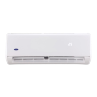
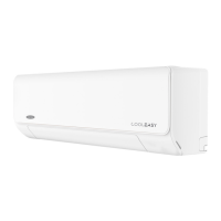
Details on the functions and operations of the indoor unit.
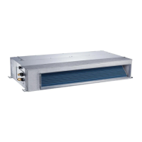
Details on the functions and operations of the outdoor unit.
Physical dimensions of the indoor unit, including width, height, and depth.
Physical dimensions of the outdoor unit, including width, height, depth, and pipe lengths.
Diagram illustrating the refrigerant flow for cooling-only operation.
Diagram illustrating the refrigerant flow for heat pump operation.
Defines the operational temperature limits for cooling mode.
Defines the operational temperature limits for heating mode.
Electrical connections and layout for the indoor unit.
Electrical connections and layout for the outdoor unit.
Specifies torque values for various pipe diameters during installation.
Guidelines for selecting and connecting power cords based on unit capacity.
Details on allowable pipe lengths and elevation differences for installation.
Procedure for removing air and moisture from the refrigerant piping system.
Method for recovering refrigerant by operating the compressor before disconnection.
Procedure for purging air from the system after re-installation.
Steps to balance refrigerant charge between indoor and outdoor units.
Process of removing non-condensable gases and moisture using a vacuum pump.
Procedure for charging the system with the correct amount of refrigerant.
Definitions of symbols and abbreviations used in electronic control descriptions.
Overview of various electronic functions and modes of the air conditioner.
Details on the protective functions and safety mechanisms of the unit.
Specific protection features like compressor delay, sensor protection, and fan speed control.
Explanation of the fan-only operational mode.
Details on the compressor and fan operation during cooling mode.
Explanation of the dehumidification function, including valve and fan actions.
General operation, valve actions, and compressor/fan control in heating mode.
Conditions, timing, and actions related to the defrosting cycle in heating mode.
How the unit automatically selects cooling, heating, or fan-only modes.
Details on activating and operating the forced cooling mode.
Features and operation of the sleep mode for energy saving.
Functionality of the turbo mode for rapid cooling.
How the unit resumes operation after a power failure.
Table listing operational parameters and model-specific values for different units.
Explanation of operation indicators on the display board for different modes.
Table of failure phenomena and corresponding indicator status for diagnosis.
Flowchart to diagnose operational issues when no indicators are lit.
Diagnosing issues based on operational phenomena and specific lamp states.
Diagnosing faults indicated by specific combinations of operation and timer lamp states.
Table correlating temperature (Celsius) with resistance (kΩ) for sensors.
| Brand | Carrier |
|---|---|
| Model | 42QCR012713 |
| Category | Air Conditioner |
| Language | English |