Do you have a question about the Carrier 42QTD012DS and is the answer not in the manual?
Explains the coding system used for product model numbers.
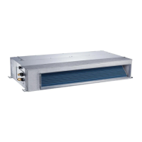
Provides outline dimensions and sizing for ducted units.
Specifies the required clearances for installing ducted indoor units.
Presents static pressure performance curves for ducted units.
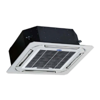
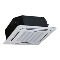
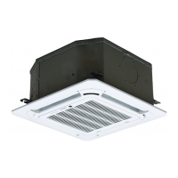
Provides outline dimensions for 12K and 18K cassette units.
Specifies the required clearances for installing cassette indoor units.
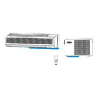
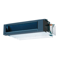
Provides outline dimensions for under-ceiling indoor units.
Specifies the required clearances for installing under-ceiling indoor units.
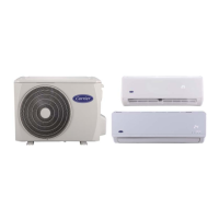
Provides outline dimensions for outdoor units.
Specifies the required clearances for installing outdoor units.
Guide to removing the electronic control box and its components.
Steps for removing the display board from the unit.
Procedure for removing the Printed Circuit Board (PCB).
Steps to remove the fan capacitor.
Guide to removing the fan motor assembly.
Procedure for removing the water collector assembly.
Steps for removing the evaporator unit.
Steps to open the grille and remove the air filter.
Guide to removing the unit panel and associated components.
Steps to disassemble and remove the display board.
Procedure for removing the swing motor assembly.
Steps to remove the main Printed Circuit Board (PCB).
Steps to remove the fan wheel from the assembly.
Guide to removing the fan motor.
Procedure for removing the water collecting assembly.
Steps to remove the draining pump.
Guide to removing the evaporator from the unit.
Steps to release lockers and remove air outlet grilles.
Guide to removing the control PCB and its cover.
Procedure for removing the fan motor and fan wheel assembly.
Steps to remove the display PCB.
Guide to removing the vertical swing motor.
Steps to remove the evaporator assembly.
Steps to remove the top and front panels of the outdoor unit.
Guide to removing the fan assembly, including the nut and connector.
Procedure for removing wiring covers, boards, and wires.
Steps for removing the compressor, including pipes and mounting nuts.
Shows wiring connections for various indoor unit models.
Illustrates wiring connections for outdoor unit models.
Important safety warnings related to electrical components and discharge.
Lists and defines error codes and sensor abbreviations used in the system.
Diagnoses and provides solutions for common indoor unit error codes.
Diagnoses and provides solutions for common outdoor unit error codes.
| Cooling Capacity (Ton) | 1 Ton |
|---|---|
| Type | Split System |
| Cooling Capacity | 12000 BTU/hr |
| Refrigerant | R410A |
| Power Supply | 1 Phase |