15
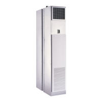
Fig. 14 — 42SJ Unit Installation
7. Attach unit risers:
NOTE: Submittals and product literature detailing unit opera-
tion, controls, and connections should be thoroughly reviewed
BEFORE beginning the connection and testing of risers and pip-
ing. The supply and return connections are marked on the coil
stub-outs and the valve package with an “S” meaning supply or
inlet and “R” meaning return or outlet indicating flow direction
to and from the coil. Blue letters mark the chilled water connec-
tions and red letters mark the hot water connections.
a. Each riser has a 3-in. swaged portion at top and suf-
ficient extension at bottom for an inserted length of
approximately 2 inches. This unit-to-unit joint is
NOT intended for full bottoming in the joint, but
allows for variations in floor-to-floor dimensions
and for correct riser positioning.
If job requires that unit risers be supplemented with
between-the-floor extensions, pieces may be field-
supplied or factory-supplied. If factory-supplied,
insulation is also provided.
b. Level unit to ensure proper coil operation and con-
densate drainage. Proper riser installation and verti-
cal positioning in the unit provides for a unit piping
run-out to the service valves, which are centered in
the access slots and level or sloping down slightly
away from the riser. This prevents condensation
from running back to the riser and possible damage
from dripping at the bottom of a riser column. Each
job has specific requirements, and satisfying those
requirements is the responsibility of the installer.
After units are positioned and riser centered in pipe
chase, make unit plumb in two directions, using unit
frame as a reference.
c. Anchor unit to building. Use bolts or lag screws
through holes provided in unit frame.
d. After all units in a stack are anchored, make unit-to-
unit riser joints. First, center each coil-to-riser line
within the expansion slot in the unit back panel.
Each riser joint must be in vertical alignment with at
least 1-in. penetration into the swaged joint. This
condition is met if floor-to-floor dimension is as
specified and coil-to-riser lines are properly cen-
tered. Wide variations in floor-to-floor dimensions
may necessitate cutting off or extending individual
risers. Such modifications are the full responsibility
of the installing contractor.
e. Before making the riser joints, the riser insulation
must be pulled back away from the joint and pro-
tected from heat during the brazing process. The
riser joint filler material must be selected to with-
stand the total operating pressure (both static and
pumping head) to which the system will be sub-
jected. Low temperature lead alloy solders such as
“50/50” and “60/40” are normally not suitable.
8. Anchor risers as required:
a. Do not fasten risers rigidly within each unit. Risers
must be free to move within pipe chase in response
to normal vertical expansion and contraction. The
unit internal piping is designed to accommodate a
total riser vertical movement of ±
3
/
4
-in., due to ther-
mal expansion and/or contraction, when positioned
properly at the jobsite.
b. Built-in risers must be anchored at some point to
building structure. Unit design accommodates up to
1
1
/
2
-in. expansion and contraction in riser assem-
blies when positioned properly at the job-site. Risers
must be anchored to the building structure to limit
expansion and contraction movement to a maximum
of 1
1
/
2
-in. Riser anchoring and expansion compensa-
tion is not included in the factory-supplied unit and
must be field-provided. While some special riser
features are available from the factory, riser end
caps, air vents, and/or flushing loops are normally
provided on the job by the installer.
9. Test the system for leaks after the connections are com-
pleted. When testing with air or some other gas, it might
be necessary to tighten stem packing nuts on some valves
to maintain air pressure in the riser. Pressure testing ris-
ers with water should be done with the unit service
valves closed to prevent flushing debris into the unit
valve packages. This will also allow risers to be drained
down after testing in the winter to avoid freeze-up prob-
lems. In the event that leaking or defective components
are discovered, the sales representative must be notified
before any repairs are attempted. All leaks should be
repaired before proceeding with the installation.
10. After system integrity has been established, pull the riser
insulation back into place over the joint and glue or seal
to prevent sweating and heat loss or gain. Internal chilled
CAUTION
Toxic residues and loose particles resulting from manu-
facturing and field piping techniques such as joint com-
pounds, soldering flux, and metal shavings may be pres-
ent in the unit and the piping system. Special consider-
ation must be given to system cleanliness when
connecting to solar, domestic or potable water systems.
Failure to heed this warning could result in equipment
damage.
WALL STUDS
INSTALL WALL
GYPSUM
BOARD
(TO WALL AND
OVER TOP OF
UNIT)
INSTALL
GYPSUM
BOARD TO
UNIT SIDES
INSTALL
GYPSUM
BOARD TO
FACE OF
UNIT WITH
CUT OUTS
FOR SUPPLY,
RETURN AND
THERMOSTAT
IMPORTANT: Chilled water and hot water risers should
never be piped to drain down into the condensate riser. Exten-
sive water damage can occur due to drain overflow. Drain
chilled and hot water risers to a remote location away from
the unit such as sink, room or floor drains.
 Loading...


