23
STANDARD WIRING PACKAGES
Thermostatic Electric Valve Control, 2-Pipe
A thermostatically controlled 2-position valve provides supe-
rior control to fan cycling. With this control, the fan runs con-
tinuously unless it is manually switched to the OFF or AUTO
position. The fan must be on before the valve can be opened
to supply water to the coil.
This system can be used for normal 2-pipe changeover sys-
tems and can also be furnished for cooling-only or heating-
only applications by omitting the changeover and specifying
which application is intended. Wiring diagrams show typical
applications. Refer to wiring diagram on unit blower housing
for unit specific wiring.
Thermostatic 2-Pipe Auxiliary Electric Heat with Valve
Control
This system, also called twilight or intermediate season elec-
tric heat, goes a long way towards solving the spring and fall
control problems of 2-pipe systems.
Chilled water can be run late into the fall, turned on early in
the spring, and electric heat will still be available to all units
whenever required.
In winter, the system is switched over to hot water. Two
changeover devices are required for this. One device switches
the action of the thermostat and the other locks out the elec-
tric heat when hot water is in the coil.
With this system, the fan runs continuously unless manually
switched to OFF or AUTO position. Fan must be on before
thermostat can send signal to open chilled water valve or turn
on electric heater.
Two control methods are available:
1. Use the standard automatic changeover thermostat with a
dead band between heating and cooling.
2. Use a manual changeover thermostat. With this method
only one changeover is required.
Be sure to include a 2-way or 3-way electric valve with this
system.
NOTE: Wiring diagrams are for typical applications. If other
voltages for heaters or controls are specified, wiring may differ
from that shown. Refer to wiring diagram on unit blower hous-
ing for unit specific wiring.
Thermostat 2-Pipe Total Electric Heat with Valve Control
With this system, the complete heating requirement for the
space is provided by the electric heater; the water system is
never changed over for heating. It is therefore possible, just
as with 4-pipe systems, to have heating or cooling at any time
of the year.
The fan runs continuously unless it is manually switched to
OFF or AUTO position. Fan must be on before thermostat
can send signal to open chilled water valve or turn on electric
heater.
Normally, an automatic changeover thermostat with a dead
band between heating and cooling is used, but a manual
changeover thermostat is also suitable. A 2-way or 3-way
valve must also be used so that the chilled water is off when-
ever the heater is on. No changeover device to sense water
temperature is necessary.
NOTE: Wiring diagrams are for typical applications. If other
voltages for heaters or controls are specified, wiring may differ
from that shown. Refer to wiring diagram on unit blower hous-
ing for unit specific wiring.
Thermostatic Valve Control, 4-Pipe
The 4-pipe system provides the ultimate in economy and
room temperature control. Both hot water and chilled water
are available at any time.
Normally an automatic changeover thermostat is used, but a
manual changeover thermostat is also suitable. Two 2-way
valves, two 3-way valves, or one 2-way plus one 3-way valve
must be selected. An automatic changeover device to sense
water temperature is not required.
With this system, the fan runs continuously unless it is manu-
ally switched to OFF/AUTO position. Fan must be on before
thermostat can send signal to open the chilled water or hot
water valve.
NOTE: Wiring diagrams are for typical applications. If other
voltages for heaters or controls are specified, wiring may differ
from that shown. Refer to wiring diagram on unit blower hous-
ing for unit specific wiring.
Step 3 — Make Duct Connections
Install all ductwork to and from unit in accordance with proj-
ect plans, specifications, and all applicable codes. Duct con-
struction must allow unit to operate within duct external static
pressure limits as shown on job submittals. Units designed to
operate with ductwork may be damaged if operated without
intended ductwork attached.
Units provided with outside air should have some method of
low-temperature protection to prevent freeze-up. This protec-
tion may be any of several methods, such as a low tempera-
ture thermostat to close the outside air damper or a preheat
coil to temper the outside air before it reaches the unit. It
should be noted that none of these methods will adequately
protect the coil in the event of power failure. The safest meth-
od of freeze protection is to use glycol in the proper percent
solution for the coldest expected air temperature.
Insulate ductwork as required. Use flexible connections to
minimize duct-to-unit alignment problems and noise trans-
mission where specified.
The manufacturer assumes no responsibility for undesirable
system operation due to improper system design, equipment
or component selection, and/or installation of ductwork,
grilles, and other related components.
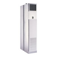
Step 4 — Frame and Finish Unit
Models 42SG, SH, SJ, SU and SM have factory enclosures
and may be finished with normally accepted wall covering.
However, drywall secured with adhesive bonding alone is not
recommended.
Concealed units are designed to have gypsum board or other
types of wall board applied directly to the unit cabinet surface
to a maximum combined thickness of
5
/
8
-inch. Use low-pro-
file sheet metal panhead screws to secure wallboard to unit
frame. Fasteners may penetrate the cabinet no more than
1
/
2
-
inch.
These fasteners must be located to avoid damage to internal
components and wiring in the same manner as anchoring fas-
teners. Do not apply sheet metal screw or nails where they
can penetrate coil, riser pipes, or electrical junction box and
raceways.
Do not secure wallboard to drain pan edges or to control box
enclosure. Condensate leaks or electrical shorts may result.
An alternate method of enclosing the unit is to frame one or
more sides with studding and apply the wall board to this
framing. This method requires specific unit features and re-
turn access panels when used on the return-air side of a unit.
Units not properly equipped will exhibit poor cooling and/or
CAUTION
Prevent dust and debris from settling in unit. If wall finish
or color is to be spray-applied, cover all openings to pre-
vent spray from entering unit. Failure to do so could result
in damage to the unit and/or the reduction of unit efficiency.
 Loading...


