11
5 INTERCONNECTION PIPES
5.1 Suspending and Mounting the Interconnection Pipes
Always insist that the interconnection pipes
are fixed appropriately by means of supports
or crossbeams, preferably both.
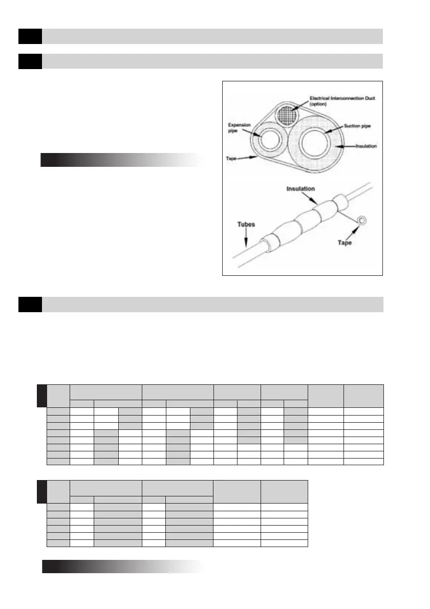
Insulate them using circular neoprene rubber
and then wrap finishing tape around them
(Fig. 16).
Since the expansion system is located in the
outdoor unit, it is necessary to create the
insulation of the expansion pipe which
interconnects the indoor unit and the outdoor
unit.
Test all of the welded and flanged
connections for leaks (maximum testing
pressure: 200 psig). Use a pressure regulator
in the nitrogen cylinder. If convenient, route
the electrical interconnection together with
the copper pipes as shown in Fig. 16.
Fig. 16 - Interconnection Pipes
5.2 Evacuating the Interconnection Pipes
The outdoor units with 20, 25 and 30,000 btu/h are produced in the factory preloaded with
the refrigerant necessary for use in a system with interconnection pipes up to 7.5m long, i.e.
the load for the outdoor unit, the load for the indoor unit and the load necessary to join an
interconnection pipe up to 7.5m long.
The outdoor units of 40, 50 and 60,000 Btu/h are produced in the factory with 1kg holding charge.
For more information regarding the additional gas load, refer to the table below:
IMPORTANT !!!
Note : * Model code for Thailand market only. Outdoor unit connection for reference only, refer to specified outdoor unit installation manual for outdoor unit pipe size.
** Gas load in additional to the normal load for a pipe 7.5m long.
Model Diameter of Suction Diameter of Diameter of Diameter of Max Change Additional
42XQ / Connections Expansion Connections Suction Pipes Expansion Pipes Drop in Level Gasload
XQA Indoor Outdoor Indoor Outdoor 0-15 15-25 0-15 15-25 (m) Above 8m** (g/m)
020 5/8" 1/2" 3/8" 1/4" 5/8" 1/4" 7 8
004* 1/2" 1/2" 1/4" 1/4" 5/8" 1/4" 7 8
025/006* 5/8" 5/8" 3/8" 1/4" 5/8" 1/4" 7 12
030 3/4" 3/4" 3/8" 3/8" 3/4" 3/8" 7 19
007*/008* 5/8" 3/4" 3/8" 3/8" 3/4" 3/8" 7 19
040/010* 3/4" 3/4" 3/8" 3/8" 3/4" 3/4" 3/8" 3/8" 7 80
050/012* 3/4" 3/4" 3/8" 3/8" 3/4" 3/4" 3/8" 3/8" 7 85
060/014* 3/4" 3/4" 3/8" 3/8" 3/4" 3/4" 3/8" 3/8" 7 90
(50Hz)
Note : ** Gas load in additional to the normal load for a pipe 7.5m long. Refer to specified outdoor unit installation manual for outdoor unit pipe size.
Model Diameter of Suction Diameter of Max Change Additional
42XQ / Connections Expansion Connections Drop in Level Gasload
XQA Indoor Outdoor Indoor Outdoor (m) Above 8m** (g/m)
020 5/8" 3/8" 7 8
025 5/8" 3/8" 7 12
030 3/4" 3/8" 7 19
040 3/4" 3/8" 7 80
050 3/4" 3/8" 7 85
060 3/4" 3/8" 7 90
(60Hz)
NOTE
For lengths of up to 8m, an additional gas load is NOT necessary.
 Loading...


