45MBCAQ: Installation Instructions
Manufacturer reserves the right to change, at any time, specifications and designs without notice and without obligations.
17
DRAINPIPE INSTALLATION
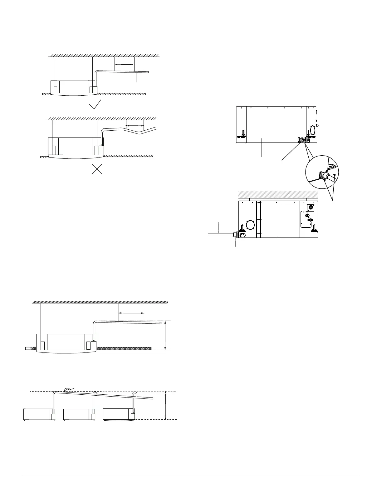
1. Install the drainpipe as illustrated in the following Figure.
Fig. 17 —Install the Drain Pipe (1)
NOTES ON DRAINPIPE INSTALLATION
• When using an extended drainpipe, tighten the indoor connection
with an additional protection tube to prevent it from pulling loose.
• The drainpipe should slope downward at a gradient of at least 1/
100 to prevent water from flowing back into the unit.
• To prevent the pipe from sagging, space hanging wires every 39-
59in (1-1.5m).
• If the outlet of the drainpipe is higher than the body’s pump joint,
provide a lift pipe for the exhaust outlet of the indoor unit. The lift
pipe must be installed no higher than 29.5in (75cm) from the
ceiling board and the distance between the unit and the lift pipe
must be less than 11.8in (30cm). Incorrect installation could cause
water to flow back into the unit and flood.
• To prevent air bubbles, keep the drain hose level or slightly tiled up
(3in/ <75mm).
Fig. 18 —Install the Drain Pipe (2)
NOTE: When connecting multiple drainpipes, install the pipes as illustrated
in the following Figure.
Fig. 19 —Connecting Multiple Drain Pipes
2. Pass the drain hose through the wall hole. Make sure the water
drains to a safe location where it will not cause water damage or a
slipping hazard.
NOTE: The drainpipe outlet should be at least 1.9in(5cm) above the ground.
If it touches the ground, the unit may become blocked and
malfunction. If you discharge the water directly into a sewer, make
sure that the drain has a U or S pipe to catch odors that might
otherwise come back into the house.
How to Install the Conduit Installation Plate (if
supplied)
1. Fix the sheath connector (not supplied) on the wire hole of the conduit
installation plate.
2. Fix the conduit installation plate on the chassis of the unit.
Fig. 20 —Install the Conduit Installation Plate
39-59in
(1-1.5m)
Downward slope
1/100
39-59in
(1-1.5m)
29.5in
(75cm)
39-59in
(1-1.5m)
The conduit
installation
plate
(not supply)
screws
Chassis
Cord conduit
The conduit
installation plate





 To Next Page