45MBCAQ: Installation Instructions
Manufacturer reserves the right to change, at any time, specifications and designs without notice and without obligations.
16
ELECTRICAL DATA
*Permissible limits of the voltage range at which the unit will operate satisfactorily.
LEGEND
FLA - Full Load Amps
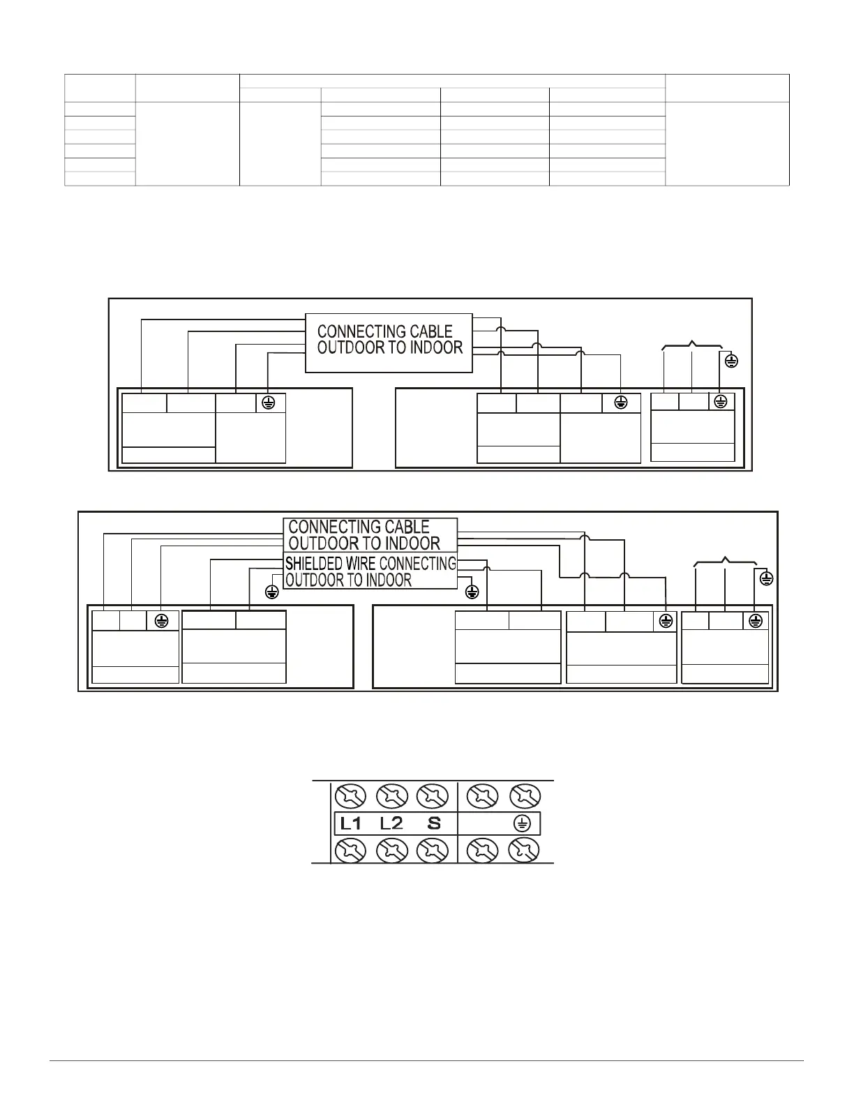
CONNECTION DIAGRAMS
Fig. 14 —Connection Diagrams (Sizes 9−24)
Fig. 15 —Connection Diagrams (Sizes 36−48)
NOTES:
1. Do not use the thermostat wire for any connection between indoor and outdoor units.
2. All connections between the indoor and outdoor units must be as shown. The connections are sensitive to polarity and will result in a fault
code.
Fig. 16 —Control and Power Wiring on Indoor Unit
UNIT SIZE
OPER. VOLTAGE
MAX / MIN*
INDOOR FAN
MAX FUSE CB AMP
V-PH-HZ FLA HP W
9
253 / 187 208--230/1/60
0.146 0.061 46
Refer to outdoor unit
installation instructions ––
Indoor unit powered by the
outdoor unit
12 0.146 0.061 46
18 0.146 0.061 46
24 0.332 0.057 58
36 0.8 0.169 1421
48 1.6 0.231 232
208/230V
Main
INDOOR
UNIT
OUTDOOR
UNIT
Indoor Unit
Power Supply
L1
L2
208/230V
1
2
208/230V
208/230V~60Hz
PE
1
2
3
Signal High
Voltage
Power to
Indoor Unit
3
Signal High
Voltage
Power Supply
Power Supply
208/230V
Main
INDOOR
UNIT
OUTDOOR
UNIT
Indoor Unit
Power Supply
L1 L2
Nonpolar RS-485
communication
Low voltage
S1 S2
Nonpolar RS-485
communication
Low voltage
S1 S2
Power to
Indoor Unit
L1
L2
208/230V
(1)L1
(2)L2
208/230V
208/230V~60Hz
PE
Power Supply
Power Supply
 Loading...