21
Humidi--MiZer
R
Control Connections
Humidi--MiZer – Space RH Controller —
NOTE: The Humidi--MiZer is a factory installed option
which is only available for units equipped with belt--drive
motors. Humidi--MiZer is not available for single phase
(--3 voltage code) models.
The Humidi--MiZer dehumidification system requires a
field--supplied and --installed space relative humidity
control device. This device may be a separate humidistat
control (contact closes on rise in space RH above control
setpoint) or a combination thermostat--humidistat control
device such as Carrier’s EDGE
R
Pro Thermidistat with
isolated contact set for dehumidification control. The
humidistat is normally used in applications where a
temperature control is already provided (units with
PremierLinkt control).
To connect the Carrier humidistat (HL38MG029):
1. Route the humidistat 2--conductor cable (field--sup-
plied) through the hole provided in the unit corner
post.
2. Feed wires through the raceway built into the corner
post (see Fig. 36) to the 24--v barrier located on the
left side of the control box. The raceway provides the
UL--required clearance between high--voltage and
low--voltage wiring.
3. Use wire nuts to connect humidistat cable to two
PINK leads in the low–voltage wiring as shown in
Fig. 39.
To connect the Thermidistat device (33CS2PPRH--01):
1. Route the Thermidistat multi--conductor thermostat
cable (field--supplied) through the hole provided in
the unit corner post.
2. Feed wires through the raceway built into the corner
post (see Fig. 36) to the 24--v barrier located on the
left side of the control box. The raceway provides the
UL--required clearance between high--voltage and
low--voltage wiring.
3. The Thermidistat has dry contacts at terminals D1
and D2 for dehumidification operation (see Fig. 40).
The dry contacts must be wired between CTB
terminal R and the PINK lead to the LTLO switch
with field--supplied wire nuts. Refer to the installation
instructions included with the Carrier Edge
Thermidistat device (Form 33CS--65SI or latest) for
more information.
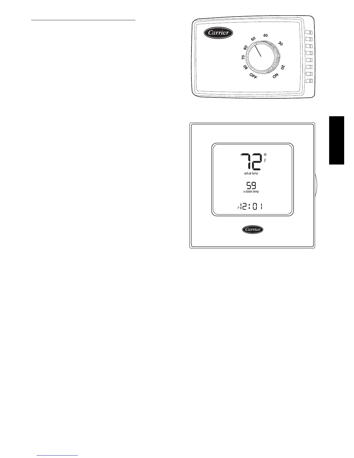
% RELATIVE HUMIDITY
C09295
Fig. 37 -- Accessory Field--Installed Humidistat
®
C09296
Fig. 38 -- EDGE Pro Thermidistat
48HC

 Loading...


