4
Removing the Return Air Filters
1. Remove the return air filter and indoor coil access
panel. See Fig. 1.
2. Reach inside and remove filters from the filter rack.
3. Replace these filters as required with similar replace-
ment filters of same size.
4. Re−install the return air filter and indoor coil access
panel.
Outdoor Air Hood
Outside air hood inlet screens are permanent
aluminum−mesh type filters. See Fig. 2. Inspect these
screens for cleanliness. Remove the screens when
cleaning is required. Clean by washing with hot
low−pressure water and soft detergent and replace all
screens before restarting the unit. Observe the flow
direction arrows on the side of each filter frame.
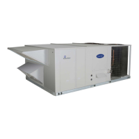
Economizer Inlet Air Screen
This air screen is retained by spring clips under the top
edge of the hood. (See Fig. 3.)
CLEANABLE
ALUMINUM
SCREEN
HOOD
FILTER
CLIP
OUTSIDE
AIR
BAROMETRIC
RELIEF
DIVIDER
17 1/4
(438 mm)
C06027
Fig. 3 − Inlet Air Screen Installation
Remove screens be removing the screws in the horizontal
clips on the leading edge of the hood. Slide the filters out.
See Fig. 3.
Install the filters by sliding clean or new filters into the
hood side retainers. Once positioned, re−install the
horizontal clips.
SUPPLY FAN (BLOWER) SECTION
ELECTRICAL SHOCK HAZARD
Failure to follow this warning could cause personal
injury or death.
Before performing service or maintenance operations
on the fan system, shut off all unit power and
Lockout/Tagout the unit disconnect switch. DO NOT
reach into the fan section with power still applied to
the unit.
!
WARNING
Supply Fan Assembly
The supply fan system consists of two forward−curved
centrifugal blower wheels mounted on a solid blower shaft
that is supported by two greasable pillow block concentric
bearings. A fixed−pitch driven fan pulley is attached to
the fan shaft and an adjustable−pitch driver pulley is
mounted on the motor. The pulleys are connected using a
V−belt. (See Fig. 4.)
MOTOR
V-BELT
MOTOR ADJUSTMENT
BOLTS (4)
JACKBOLT LOCKING NUT (2)
MOTOR MOUNTING PLATE
JACKBOLT (2)
BLOWER 15” X 17”
BLOWER
SHAFT
BLOWER
18” X 15”
C12260
Fig. 4 − Belt Drive Motor Mounting
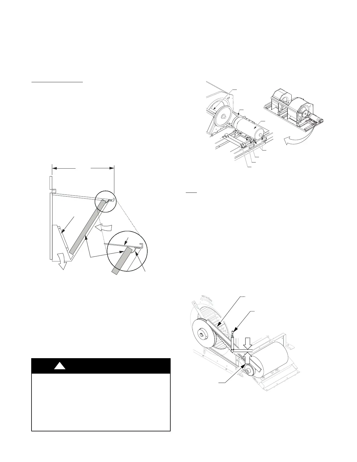
Belt
Check the belt condition and tension quarterly. Inspect the
belt for signs of cracking, fraying or glazing along the
inside surfaces. Check belt tension by using a spring−force
tool, such as Browning’s “Belt Tension Checker” (p/n
1302546 or equivalent tool); tension should be 6−lbs at a
5/8−in. (1.6 cm) deflection when measured at the center
line of the belt span. This point is at the center of the belt
when measuring the distance between the motor shaft and
the blower shaft. See Fig. 5.
NOTE: Without the spring−tension tool, place a straight
edge across the belt surface at the pulleys, then push down
on the belt at mid−span using one finger until a 1/2−in.
(1.3 cm) deflection is reached.
BROWNING BELT
TENSION CHECKER
STRAIGHTEDGE
1/2”
(1.3 cm)
BELT
DEFLECTION
Fig. 5 − Checking Blower Moter Belt Tension
C12093
Adjusting the Belt Tension
Use the following steps to adjust the V−belt tension. See
Fig. 4.
 Loading...


