6
Bearings
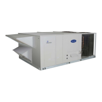
This fan system uses bearings featuring concentric split
locking collars. The collars are tightened through a cap
screw bridging the split portion of the collar. The cap
screw has a Torx T25 socket head. To tighten the locking
collar: Hold the locking collar tightly against the inner
race of the bearing and torque the cap screw to 65−70
in−lb (7.4−7.9 Nm). See Fig. 7.
LOCKING COLLAR
T-25 TORX SOCKET
HEAD CAP SCREW
C11505
Fig. 7 − Tightening Locking Collar
STAGED AIR VOLUME (SAV) CONTROL:
2−SPEED FAN WITH VARIABLE
FREQUENCY DRIVE (VFD)
Staged Air Volume (SAV) Indoor Fan Speed
System
NOTE: The SAV option is not available on units with
Humidi−MiZer adaptive humidification system.
The SAV system utilizes a Fan Speed control board and
Variable Frequency Drive (VFD) to automatically adjust
the indoor fan motor speed in sequence with the unit’s
ventilation, cooling and heating operation. Conforming to
ASHRAE 90.1 2010 Standard Section 6.4.3.10.b, during
the first stage of cooling operation the SAV system will
adjust the fan motor to provide two- thirds (2/3) of the
design airflow rate for the unit. When the call for the
second stage of cooling is required, the SAV system will
allow the design airflow rate for the unit established
(100%). During the heating mode, the SAV system will
allow total design airflow rate (100%) operation. During
ventilation mode, the SAV system will operate the fan
motor at 2/3 speed.
Identifying Factory Option
This supplement only applies to units that meet the
criteria detailed in Table 1. If the unit does not meet that
criteria, discard this document.
Table 1 — Model−Size / VFD Option Indicator
Model / Sizes
Position in
Model Number
VDP
FIOP Indicator
48TC 17 − 28 17 G, J
NOTE: See Fig. 10 for an example of typical Model
Number Nomenclature. See Appendix I for a complete
model number nomenclature display.
Unit Installation with SAV Option
48TC Rooftop—Refer to the base unit installation
instructions for standard required operating and service
clearances.
NOTE: The Remote VFD Keypad is a field-installed op
tion. It is not included as part of the Factory installed VFD
option. See “Variable Frequency Drive (VFD) Installa
tion, Setup and Troubleshooting Supplement” for wiring
schematics and performance charts and configuration. See
Fig. 8 for location of the (VFD) as mounted on the various
48TC models.
Variable
Frequency
Drive (VFD)
C11531
Fig. 8 − VFD Location for 48TC 15–27.5 Units
ADDITIONAL VFD INSTALLATION
AND TROUBLESHOOTING
Additional installation, wiring and troubleshooting infor
mation for the VFD can be found in the following manu
als: “Variable Frequency Drive (VFD) Installation, Setup
and Troubleshooting Supplement.”
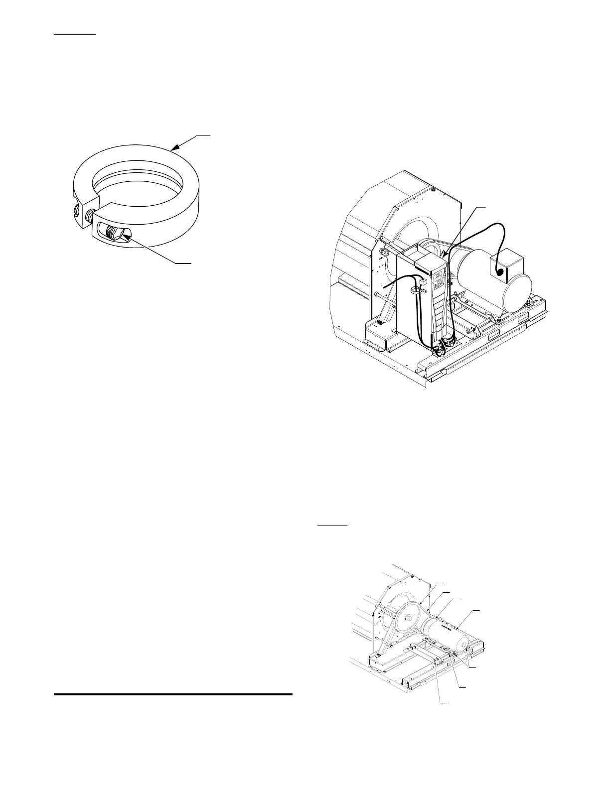
Motor
When replacing the motor, use the following steps. See
Fig. 9.
BLOWER PULLEY
V-BELT
MOTOR PULLEY
MOTOR
MOTOR MOUNTING
BOLTS (4)
JACK BOLT
JAM NUT (2)
JACK BOLT (2)
C12034
Fig. 9 − Replacing Belt Driven Motor
 Loading...


