10
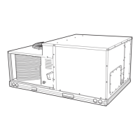
Fig. 6B — Base Unit Dimensions — 48TM007
NOTES:
1. Dimensions in [ ] are in millimeters.
2. Center of gravity.
3. Direction of airflow.
4. On vertical discharge units, ductwork to be attached to accessory roof
curb only. For horizontal discharge units, field-supplied flanges should be
attached to horizontal discharge openings, and all ductwork should be
attached to the flanges.
5. Minimum clearance (local codes or jurisdiction may prevail):
a. Between unit, flue side and combustible surfaces, 36 in., 18 in. when
using accessory flue discharge deflector.
b. Bottom of unit to combustible surfaces (when not using curb), 1 inch.
Bottom of base rail to combustible surfaces (when not using curb)
0 inches.
c. Condenser coil, for proper airflow, 36 in. one side, 12 in. the other.
The side getting the greater clearance is optional.
d. Overhead, 60 in. to assure proper condenser fan operation.
e. Between units, control box side, 42 in. per NEC (National Electrical
Code).
f. Between unit and ungrounded surfaces, control box side, 36 in. per
NEC.
g. Between unit and block or concrete walls and other grounded sur-
faces, control box side, 42 in. per NEC.
h. Horizontal supply and return end, 0 in. when the alternate conden-
sate drain is used.
6. With the exception of the clearance for the condenser coil and combus-
tion side as stated in notes 5a, b and c, a removable fence or barricade
requires no clearance.
7. Units may be installed on combustible floors made from wood or Class A,
B, or C roof covering material if set on base rail.
8. The vertical center of gravity is 1
′
-6
″
[457] up from the bottom of the base
rail.
 Loading...