bus is entirely within one building, the resulting continuous
shield must be connected to a ground at one point only.If
the communication bus cable exits from one building and
enters another, the shields must be connected to grounds at
the lightning suppressor in each building where the cable
enters or exits the building (one point per building only).
To connect the unit to the network:
1. Turn off power to the control box.
2. Cut the CCN wire and strip the ends of the red (+), white
(ground), and black (−) conductors. (If a different
network color scheme is used, substitute appropriate colors.)
3. Remove the 3-pin male plug from the base module in the
main control box, and connect the wires as follows:
a. Insert and secure the red (+) wire to terminal 1 of the
3-pin plug.
b. Insert and secure the white (ground) wire to ter-
minal 2 of the 3-pin plug.
c. Insert and secure the black (−) wire to terminal 3 of
the 3-pin plug.
4. Insert the plug into the existing 3-pin mating connector
on the base module in the main control box.
Step 8 — Make Outdoor-Air Inlet Adjustments
ECONOMIZER
NOTE: If accessory power exhaust or barometric relief pack-
ages are being added to the unit, install power exhaust or
barometric relief before installing economizer hoods.
Economizer Hood Assembly — The economizer hood is
shipped in a package secured to the outside of the unit and
must be field-assembled. There are 2 hoods on every unit.
The 50EWQ units are side supply and side return. The
return duct limits access to economizer filters from below.
Filter tracks (mounting angle without tabs) must be installed
correctly to allow access to economizer filters from each side.
Perform the following procedure to assemble the econo-
mizer hood.
NOTE: Before assembly of the economizer hood, check along
the outer edges of the economizer assembly for any seal strip
protruding past the flanges. Trim the excess seal strip so that
it is flush with the economizer assembly flanges.
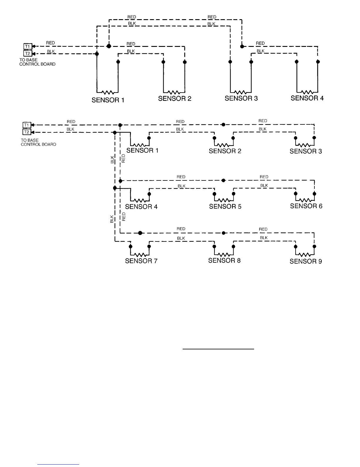
SPACE TEMPERATURE AVERAGING — 4 SENSOR APPLICATION
SPACE TEMPERATURE AVERAGING — 9 SENSOR APPLICATION
Fig. 15 — Space Temperature Averaging Wiring
14
 Loading...


