Table 2 — Evaporator Fan Motor Data (Units with Starting Serial Numbers 4197 and Later)
UNIT
SIZE
50EJQ,
EWQ
MOTOR
HP
MOTOR
SHAFT
DIAM.
(in.)
FAN
SHAFT
SPEED
(rpm)
MOTOR
SHEAVE
MOTOR
SHEAVE
PITCH
DIAM.
(in.)
MOTOR
BUSHING
DIAM.
(in.)
FAN
SHEAVE
FAN
SHEAVE
PITCH
DIAM.
(in.)
FAN
BUSHING
DIAM.
(in.)
BELT
(Qty)
OUTSIDE
BELT
LENGTH
(in.)
BELT
TENSION
(lb @
.24 in.)
024
5 1.12 717 BK55 4.8 None-1.125 1B5V124 12.4 B-1.9375 BX59 62 5.10
10 1.38 924 2BK50 4.4 None-1.375 2B5V86 8.6 B-1.9375 (2) BX51 54 5.21
15 1.62 1096 2B5V56 5.7 B-1.625 2B5V90 9.1 B-1.9375 (2) 5VX530 53 6.00
028
7.5 1.38 773 BK60H 5.4 H-1.375 1B5V124 12.4 B-1.9375 BX59 62 6.48
10 1.38 962 1B5V60 6.1 H-1.375 1B5V110 11.1 B-1.9375 5VX590 59 7.37
15 1.62 1106 2B5V54 5.5 B-1.625 2B5V86 8.7 B-1.9375 (2) 5VX530 53 6.12
NOTE: Motor shaft speed is 1750 rpm. The fan shaft diameter is 1
15
⁄
16
inches.
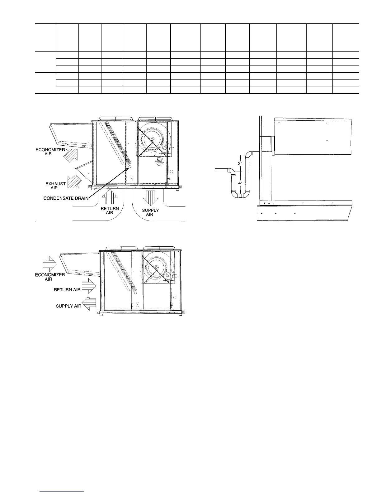
Step5—TrapCondensate Drain — See Fig. 2, 3,
and 7 for drain location. Condensate drain is open to the at-
mosphere and must be trapped. Install a trapped drain at the
drain location. One 1-in. FPT coupling is provided inside
unit indoor section for condensate drain connection. A trap
at least 4-in. deep must be used. Trap must be installed to
prevent freeze-up.
Condensate pans are sloped so that water will completely
drain from the condensate pan to comply with indoor air qual-
ity guidelines.
Step 6 — Controls Options — The control options
that the units can provide are based on the following param-
eters: CV (constant volume) operation; stand-alone unit with
field-supplied sensors installed; as a system via the Carrier
Comfort System (TEMP); optional electronic expansion board
installed, linked to the Carrier Comfort Network; and avail-
ability of a computer and software (ComfortWorks™, Build-
ing Supervisor, and Service Tool) or accessory LID-2B to
access the base control board. See Table 3.
NOTE: Access to the base control board allows unit occu-
pancy schedules, unit timeclock, and various set points to be
changed from their factory-defined default settings.
The units, as shipped, are operable as stand-alone units,
using either a standard (mechanical or electronic) 2-stage heat,
2-stage cool thermostat, or with an electronic room sensor
and a timeclock to establish unit start and stop times.
With a standard thermostat (programmable is optional),
heating and cooling operation is set by space temperature.
With a space sensor and timeclock, the unit will operate
at default values unless they are changed using appropriate
input devices. The space sensor senses space temperature and
may be equipped with a timed override feature, which
allows unit operation during unoccupied periods.
The space sensors may be used in multiples of 4 or 9 to
achieve space temperature averaging. The use of a space sen-
sor also allows the unit to be turned on and off from a
remote signal.
FEATURES WITH THERMOSTAT CONTROL OF UNIT
• two-stage heating (if installed)
• two-stage cooling
• control of unit using Y1, Y2, W1, W2, and G thermostat
inputs
• control of the indoor fan
• outdoor-air temperature/supply-air temperature monitoring
• control of outdoor fan based on outdoor-air temperature
• control of modulating economizer damper to provide free
cooling when outdoor conditions are suitable, using
supply-air temperature as a control point
Fig. 5 — Air Distribution — Thru-the-Bottom
Fig. 6 — Air Distribution — Thru-the-Side
Fig. 7 — Condensate Drain Connections
(Typical Roof Curb or Slab Mount Shown)
7
 Loading...


