FEATURES WITH SENSOR CONTROL OF UNIT (Net-
work Applications) — The base control board provides, as
standard, a connection for integration into a Carrier Comfort
Network.
When the unit is accessed via a PC equipped with
ComfortWorks™, Building Supervisor, or Service Tool soft-
ware or accessory LID-2B, the following features can be
accessed:
• on-board timeclock can be programmed
• occupancy schedules can be programmed
• unit set points can be changed
• alarms can be monitored
This access is available on the base control board via a
RJ-11 phone jack or a 3-wire connection to the communi-
cation bus. See Fig. 10. The timeclock has a 10-hour minimum
back-up time to provide for unit power off for servicing unit
or during unexpected power outages. For complete Carrier
Comfort System (CCS) or Carrier Comfort Network (CCN)
features and benefits, refer to the product literature.
Step 7 — Make Electrical Connections
POWER WIRING — Units are factory wired for the voltage
shown on the unit nameplate. The main terminal block is
suitable for use with aluminum or copper wires and is sized
for single-point electric heat.
When installing units, provide a disconnect per NEC
(National Electrical Code) of adequate size (MOCP [maxi-
mum overcurrent protection] of unit is on the informative
plate). All field wiring must comply with NEC and all local
codes. Size wire based on MCA (minimum circuit amps) on
the unit informative plate. See Fig. 11 for power wiring con-
nections to the unit power terminal block and equipment ground.
The main power terminal block is suitable for use with
aluminum or copper wire. See Fig. 11. Units have circuit
breakers for compressors, fan motors, and control circuit. If
required by local codes, provide an additional disconnect,
per NEC and local codes requirements, of adequate size
(Table 4). Whenever external electrical sources are used, unit
must be electrically grounded in accordance with local codes,
or in absence of local codes, with NEC, ANSI (American
National Standards Institute) C1-latest year.
All field wiring must comply with NEC and local code
requirements.
FIELD POWER SUPPLY — Unit is factory wired for volt-
age shown on nameplate. See Table 4 for electrical data.
Field wiring can be brought into the unit from bottom
(through basepan and roof curb) or through side of unit (cor-
ner post next to control box).
A3
1
⁄
2
-in. NPT coupling for field power wiring and a
3
⁄
4
-in. NPT coupling for 24-v control wiring are provided in
basepan. In the side post, there are two 2
1
⁄
2
-in. knockouts for
the field power wiring. See Fig. 2 and 3. If control wiring is
to be brought in through the side of unit, a
7
⁄
8
-in. diameter
hole is provided in the condenser side post next to the con-
trol box.
If disconnect box is mounted to corner post, be careful
not to drill any screws into the condenser coil.
Routing Through Bottom of Unit — If wiring is brought in
through bottom of unit, use field-supplied watertight conduit
to run power wiring from basepan out through bottom
3
1
⁄
2
-in. hole to the disconnect box and back into unit to the
main control box.
Use strain relief going into control box through 2
1
⁄
2
-in.
diameter hole provided. After wires are in unit control box,
connect to power terminal block (see Power Wiring section
on this page).
Low-voltage wiring must be run in watertight conduit from
the basepan to control box and through
7
⁄
8
-in. diameter hole
provided in bottom of unit control box. Field-supplied strain
relief must be used going into the box. After wiring is in
control box, make connections to proper terminals on ter-
minal blocks (see Field Control Wiring section on page 11).
Install conduit connector in unit basepan or side panel open-
ings provided. Route power and ground lines through con-
nector to connections in unit control box as shown on unit
wiring diagram and Fig. 11.
Routing Through Side of Unit — Route power wiring in
field-supplied watertight conduit into unit through 2
1
⁄
2
-in. hole.
Strain relief (field supplied) must be used in hole.
Use field-supplied strain relief going into control box through
2
1
⁄
2
-in. diameter hole provided. After wires are in unit con-
trol box, connect to power terminal block (see Power Wiring
section on this page).
Bring low-voltage control wiring through factory-drilled
7
⁄
8
-in. diameter hole in condenser side post. Use strain relief
going into
7
⁄
8
-in. diameter hole in bottom of unit control box.
After wiring is in control box, make connection to proper
terminals on terminal blocks (see Field Control Wiring sec-
tion on page 11). See Fig. 11.
The unit must be electrically grounded in accordance
with local codes and NEC ANSI/NFPA 70 (National Fire
Protection Association).
Operating voltage to compressor must be within voltage
range indicated on unit nameplate. On 3-phase units, volt-
ages between phases must be balanced within 2% and the
current must be balanced within 10%.
Use the formula in the notes in Table 4 to determine the
percentage of voltage imbalance.
IMPORTANT: If the supply voltage phase imbalance
is more than 2%, contact your local electric utility com-
pany immediately.
Unit failure as a result of operation on improper line volt-
age or excessive phase imbalance constitutes abuse and may
cause damage to electrical components.
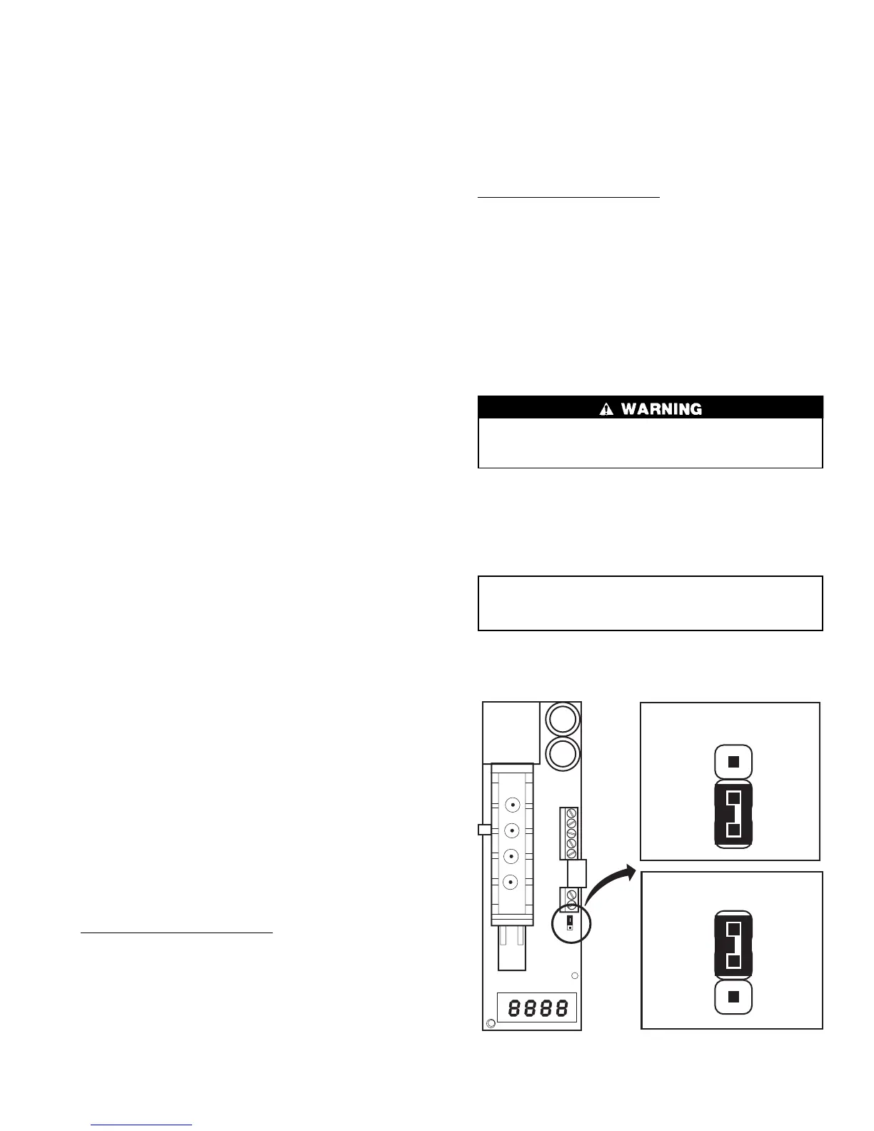
JUMPER CONNECTION
FOR VOLTAGE OUTPUT
JUMPER CONNECTION
FOR CURRENT OUTPUT
Fig. 9 — Indoor Air Quality Sensor Configuration
9
 Loading...


