8
TROUBLESHOOTING THE ECM MOTOR
EcoBlue™ motors are designed with several built-in protections
included in the motor software. If the motor detects a fault it will
safely shut down. For temperature related faults the motor re-
quires a line voltage reset to continue operation. For all others,
the motor will resume operation automatically as soon as the
fault condition is cleared. See Table 2 for a complete list.
Troubleshooting the motor requires a voltmeter.
1. Disconnect main power to the unit.
2. Disconnect motor plug in supply section of the unit.
3. Restore main unit power.
4. Check for proper line voltage at motor power leads Black
(PL1-1), Yellow (PL1-2), and Blue (PL1-3). Blue is only
present on 3-phase motors. See the following table.
5. Disconnect main power.
6. Reconnect motor plug in supply section of unit.
7. Restore main power.
8. Check for proper motor control voltage signal of 9.7 vdc
to 10.3 vdc at IFM-1 and IFM-3 on Unit Control Board
(UCB). See Fig. 10.
9. Using a jumper wire from unit control terminals R to G,
engage motor operation.
10. Verify control signal from user speed selection switch by
placing voltmeter taps in provided terminals marked vdc.
Signal should be between 3.8 vdc and 10.3 vdc.
11. If the motor does not start and run, remove the fan assem-
bly and replace the motor with one having the same part
number. Do not substitute with an alternate design motor
as the voltage/speed programming will not be the same as
that on an original factory motor.
Fig. 10 — Supply Fan Control Wiring Diagram
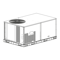
Removing the Motor and Fan Assembly
NOTE: Due to press fit design of composite Rotor on Motor, it is
highly recommended that any time a motor is replaced the fan ro-
tor is replaced as well. The rest of the assembly may be reused.
See Fig. 11.
1. Unplug motor harness from control box harness and cut
wire tie at the fan deck.
2. Unplug connectors from stator temperature limit switch.
3. Remove 2 screws at front of stator on fan deck.
4. Slide fan assembly forward a couple of inches to clear rear
brackets and lift assembly out.
Fig. 11 — Fan Assembly Removal
Table 2 — Fault Condition/Reset Trigger
FAULT
CONDITION
RESET
TRIGGERS
DESCRIPTION
Phase Failure Automatic
One phase is missing or imbalanced.
In this case the motor will come to a
stop and then automatically restart
when all phases are present.
Locked/
Blocked Rotor
Automatic
The rotor is blocked. Once the locking
mechanism has been removed, the
motor will automatically restart.
Motor
Overheated
Manual
The motor will stop in the event the
motor overheats. In this case there
has to be a manual restart.
Power Module
Overheated
Manual
The motor will stop in the event the
electronics overheat. In this case
there has to be a manual restart.
Line Under-
voltage
Automatic
Once the line voltage returns within
permitted operating range, the fan will
automatically restart.
Communication
Error
Automatic
Internal communication error of the
fan’s electronics. The fan will restart
automatically, if error is cleared.
50GCQ UNIT
VOLTAGE
MOTOR VOLTAGE
MINIMUM-
MAXIMUM VOLTS
208/230 230 190-250
460 230 210-250
575 460 420-500
4
2
1
3
 Loading...