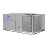
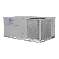
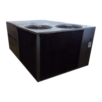
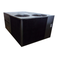
Cont ro ls , St art---Up, Operat io n
and Troubleshooting
48/50HC 04---28
Single Package Rooftop Units
with ComfortLink Controls Version 1.X
and PURONr (R---410A) Refrigerant
IMPORTANT: This literature covers 48/50HC 04--28 models with
ComfortLink Software version 1.X.
TABLE OF CONTENTS
Page
SAFETY CONSIDERATIONS 2.........................
GENERAL 3.........................................
BASIC CONTROL USAGE 3...........................
ComfortLink Control 3................................
Scrolling Marquee 3..................................
Accessory Navigator Display 4..........................
Operation 4.........................................
System Pilott and Touch Pilot Devices 4.................
CCN Tables and Display 4.............................
Conventions Used in This Manual 6......................
START--UP 6.........................................
Unit Preparation 6....................................
Compressor Mounting 6...............................
Refrigerant Service Ports 6.............................
Crankcase Heater(s) 6.................................
Compressor Rotation 6................................
Power Supply 6.....................................
Internal Wiring 6.....................................
Evaporator Fan 6....................................
Condenser Fans and Motors 7...........................
Return--Air Filters 7..................................
Outdoor--Air Inlet Screens 7............................
Accessory Installation 7...............................
Orifice Change (48HC) 7..............................
Gas Heat (48HC) 8...................................
EnergyX 8.........................................
CONTROLS QUICK SET--UP 9.........................
Control Set Point and Confirmation Log 9.................
Thermostat Control 9.................................
Space Temperature Sensor Control -- Direct Wired
(T--55 or T--56 or T--59) 9.............................
T--58 Communicating Room Sensor 9....................
CCN Linkage Control 9...............................
System Pilot -- Communication Space Sensor 9.............
Thermidistat Control 9................................
Space Humidistat Control 9............................
Relative Humidity Sensor Control 9......................
CCN Communication 9...............................
Accessories 9.......................................
Programming Operating Schedules 10....................
SERVICE TEST 12....................................
Independent Outputs 12...............................
Fan Test 12.........................................
Cooling Test 12.....................................
Humidi--MiZert Test 12..............................
Heating Test 13......................................
THIRD PARTY CONTROL 13..........................
Cooling/Heating Control 13............................
Dehumidification Control 13...........................
Remote Occupancy 13................................
Fire Shutdown 13....................................
Alarm Output 13.....................................
Economizer Damper Control 13.........................
CONTROLS OPERATION 14...........................
Display Configuration 14..............................
Unit Configuration 14.................................
Modes 14..........................................
General Operation 15.................................
Temperature Setpoint Determination 15...................
Occupancy Determination 16...........................
Cooling Operation 18.................................
Heating Operation 19.................................
Economizer 21......................................
Indoor Air Quality (IAQ) 23............................
Optional Humidi--MiZert Dehumidification System 24......
EnergyX 29........................................
Temperature Compensated Start 29.......................
Carrier Comfort Network (CCN)R Configuration 30.........
Demand Limit 30....................................
Linkage 31.........................................
Alarm Handling 31...................................
TROUBLESHOOTING 31..............................
Complete Unit Stoppage 32............................
Restart Procedure 32..................................


 Loading...