12
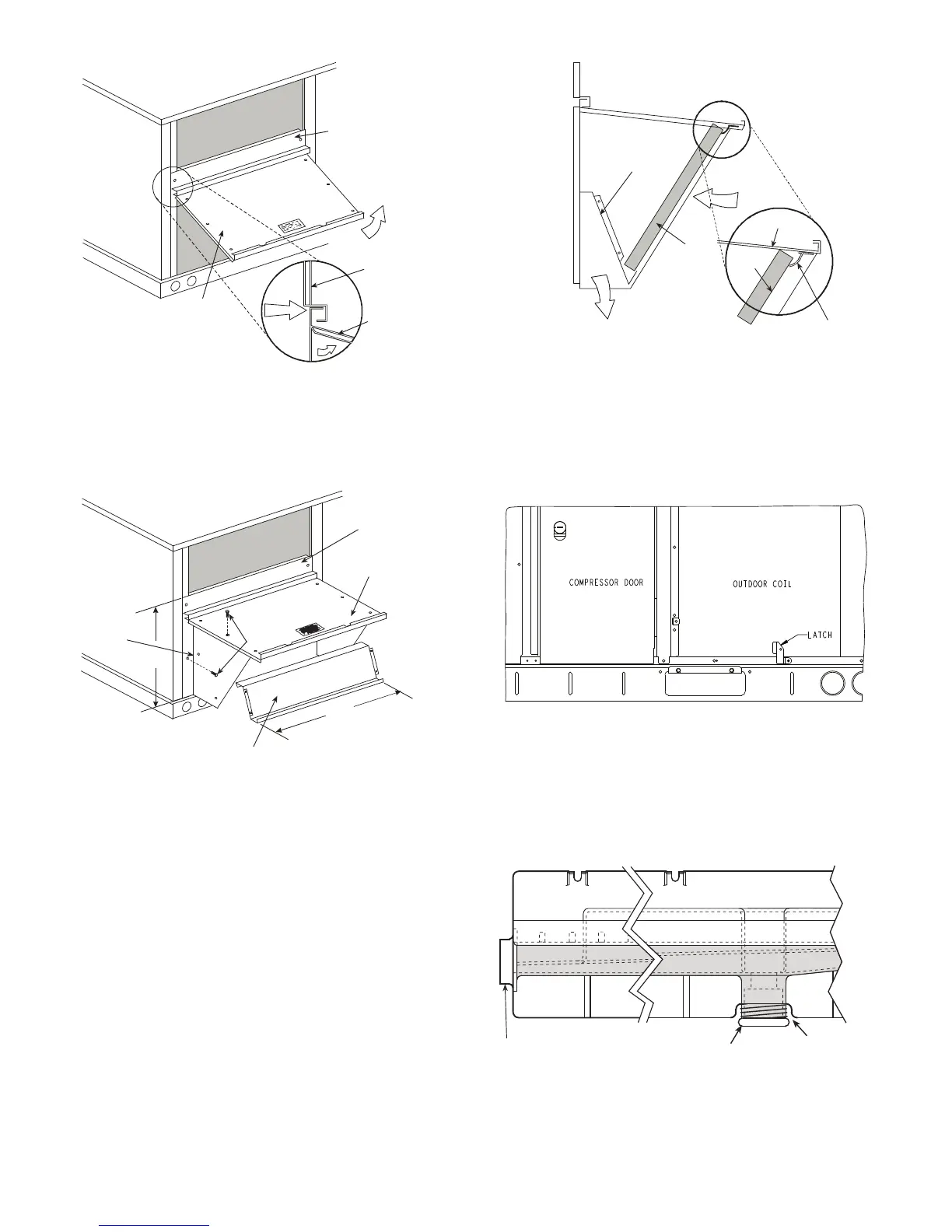
Fig. 12 — Indoor Coil Access Panel Relocation
2. Swing out indoor coil access panel and insert the hood
sides under the panel (hood top). Use the screws pro-
vided to attach the hood sides to the hood top. Use
screws provided to attach the hood sides to the unit. See
Fig. 13.
Fig. 13 — Economizer Hood Construction
3. Remove the shipping tape holding the economizer baro-
metric relief damper in place (economizer only).
4. Insert the hood divider between the hood sides. See
Fig. 13 and Fig. 14. Secure hood divider with 2 screws
on each hood side. The hood divider is also used as the
bottom filter rack for the aluminum filter.
5. Open the filter clips which are located underneath the
hood top. Insert the aluminum filter into the bottom filter
rack (hood divider). Push the filter into position past the
open filter clips. Close the filter clips to lock the filter
into place. See Fig. 14.
6. Caulk the ends of the joint between the unit top panel and
the hood top.
7. Replace the filter access panel.
Fig. 14 — Economizer Filter Installation
Step 9 — Units with Hinged Panels Only
Relocate latch shipped inside the compressor compartment
behind the hinged compressor door to location shown in
Fig. 15 after unit installation.
If the unit does not have hinged panels, skip this step and
continue at Step 10.
Fig. 15 — Compressor Door Latch Location
Step 10 — Install External Condensate Trap
and Line
The unit has one
3
/
4
-in. condensate drain connection on the
end of the condensate pan and an alternate connection on the
bottom. See Fig. 16. Unit airflow configuration does not de-
termine which drain connection to use. Either drain connec-
tion can be used with vertical or horizontal applications.
Fig. 16 — Condensate Drain Pan (Side View)
To use the alternate bottom drain connection, remove the red
drain plug from the bottom connection (use a
1
/
2
-in. square
socket drive extension) and install it in the side drain connec-
tion.
TOP
PANEL
INDOOR
COIL
ACCESS
PANEL
INDOOR
COIL
ACCESS
PANEL
CAULK
HERE
TOP
PANEL
B
TOP
PANEL
INDOOR COIL
ACCESS PANEL
19 1/16”
SCREW
HOOD DIVIDER
LEFT
HOOD
SIDE
33 3/8”
(848mm)
(483mm)
DIVIDER
BAROMETRIC
RELIEF
CLEANABLE
ALUMINUM
FILTER
FILTER
HOOD
FILTER
CLIP
OUTSIDE
AIR
DRAIN
(FACTORY-INSTALLED)
PLUG
CONDENSATE PAN (SIDE VIEW)
STANDARD
SIDE DRAIN
ALTERNATE
BOTTOM DRAIN
 Loading...


