17
NOTE: Check all factory and field electrical connections for
tightness.
FIELD CONTROL WIRING
The 50KC unit requires an external temperature control de-
vice. This device can be a thermostat (field-supplied) or a
PremierLink controller (available as factory-installed option
or as field-installed accessory, for use on a Carrier Comfort
Network
®
or as a stand-alone control) or the RTU Open Con-
troller for Building Management Systems using non-CCN
protocols (RTU Open is available as a factory-installed op-
tion only).
THERMOSTAT
Select a Carrier-approved accessory thermostat. When elec-
tric heat is installed in the 50KC unit, the thermostat must be
capable of energizing the G terminal (to energize the Indoor
Fan Contactor) whenever there is a space call for heat (ener-
gizing the W1 terminal). The accessory thermostats listed on
the unit price pages can provide this signal but they are not
configured to enable this signal as shipped.
Install the accessory thermostat according to installation in-
structions included with the accessory.
Locate the thermostat accessory on a solid wall in the condi-
tioned space to sense average temperature in accordance with
the thermostat installation instructions.
If the thermostat contains a logic circuit requiring 24-v pow-
er, use a thermostat cable or equivalent single leads of differ-
ent colors with minimum of seven leads. If the thermostat
does not require a 24-v source (no “C” connection required),
use a thermostat cable or equivalent with minimum of six
leads. Check the thermostat installation instructions for addi-
tional features which might require additional conductors in
the cable.
For wire runs up to 50 ft. (15 m), use no. 18 AWG (American
Wire Gage) insulated wire [35°C (95°F) minimum]. For 50 to
75 ft. (15 to 23 m), use no. 16 AWG insulated wire [35°C
(95°F) minimum]. For over 75 ft. (23 m), use no. 14 AWG in-
sulated wire [35°C (95°F) minimum]. All wire sizes larger than
no. 18 AWG cannot be directly connected to the thermostat and
will require a junction box and splice at the thermostat.
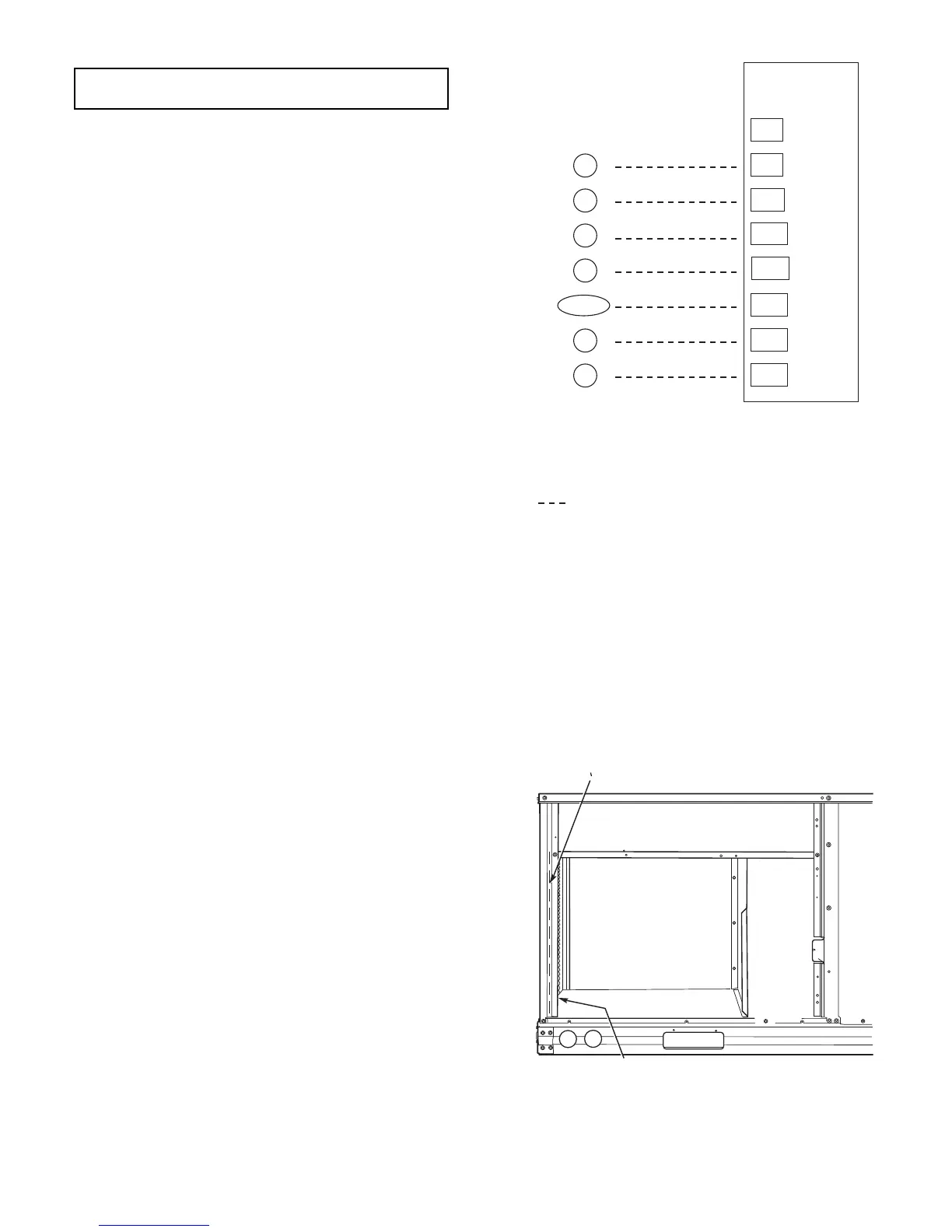
Fig. 27 — Low-Voltage Connections
UNIT WITHOUT THRU-BASE CONNECTION KIT
Pass the thermostat control wires through the hole provided
in the corner post; then feed the wires through the raceway
built into the corner post to the control box. Pull the wires
over to the terminal strip on the upper-left corner of the Con-
trols Connection Board. See Fig. 28.
NOTE: If thru-the-bottom connections accessory is used, re-
fer to the accessory installation instructions for information
on routing power and control wiring.
HEAT ANTICIPATOR SETTINGS
Set heat anticipator settings at 0.14 amp for the first stage and
0.14 amp for second-stage heating, when available.
Fig. 28 — Field Control Wiring Raceway
IMPORTANT: If the supply voltage phase imbalance is more than
2%, contact your local electric utility company immediately.
X
C
G
W2
R
C
W2
G
W1
O/B/Y2
Y2
W1
R
Y1
Y1
Typical
Thermostat
Corrections
T
H
E
R
M
O
S
T
A
T
(Note 1)
(Note 2)
(Note 3)
1. Typical multi-function marking. Follow manufacturer’s configuration
instructions to select Y2.
2. Y2 to Y2 connection required on single-stage cooling units when
integrated economizer function is desired
3. W2 connection not required on units with single-stage heating.
Field Wiring
Central
Terminal
Board
Notes:
RACEWAY
HOLE IN END PANEL (HIDDEN)
 Loading...


