14
UNITS WITH FACTORY-INSTALLED NON-FUSED DIS-
CONNECT
The factory-installed option non-fused disconnect (NFD)
switch is located in a weatherproof enclosure located under
the main control box. The manual switch handle and shaft are
shipped in the disconnect enclosure. Assemble the shaft and
handle to the switch at this point. Discard the factory test
leads (see Fig. 18).
Connect field power supply conductors to LINE side termi-
nals when the switch enclosure cover is removed to attach the
handle.
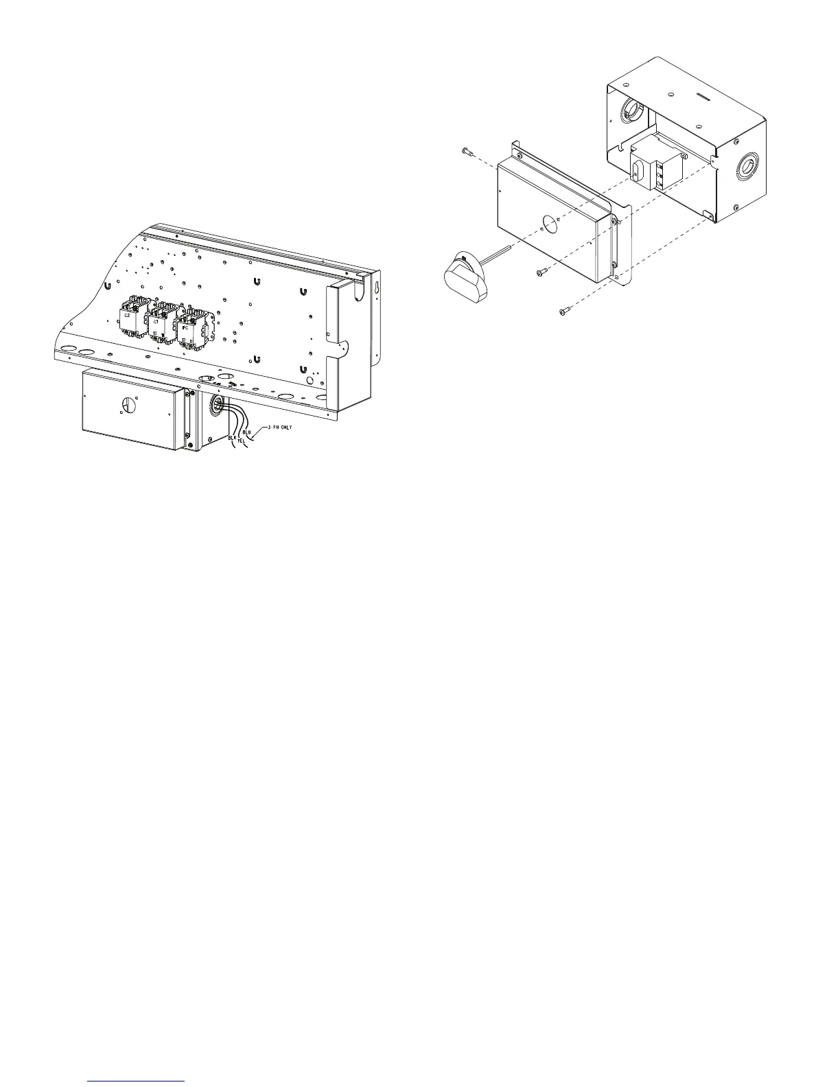
Fig. 20 — Location of Non-Fused Disconnect
Enclosure
To field install the NFD shaft and handle:
1. Remove the unit front panel (see Fig. 2).
2. Remove (3) hex screws on the NFD enclosure — (2) on
the face of the cover and (1) on the left side cover.
3. Remove the front cover of the NFD enclosure.
4. Make sure the NFD shipped from the factory is at OFF
position (the arrow on the black handle knob is at OFF).
5. Insert the shaft with the cross pin on the top of the shaft
in the horizontal position.
6. Measure from the tip of the shaft to the top surface of the
black pointer; the measurement should be 3.75 to 3.88 in.
(95 to 99 mm).
7. Tighten the locking screw to secure the shaft to the NFD.
8. Turn the handle to the OFF position with red arrow
pointing at OFF.
9. Install the handle on to the painted cover horizontally
with the red arrow pointing to the left.
10. Secure the handle to the painted cover with (2) screws
and lock washers supplied.
11. Engaging the shaft into the handle socket, re-install (3)
hex screws on the NFD enclosure.
12. Re-install the unit front panel.
Fig. 21 — Handle and Shaft Assembly for NFD
UNITS WITHOUT FACTORY-INSTALLED NON-FUSED
DISCONNECT
When installing units, provide a disconnect switch per NEC
(National Electrical Code) of adequate size. Disconnect siz-
ing data is provided on the unit informative plate. Locate dis-
connect sizing data on unit cabinet or within sight of the unit
per national or local codes. Do not cover unit informative
plate if mounting the disconnect on the unit cabinet.
ALL UNITS
All field wiring must comply with NEC and all local codes.
Size wire based on MCA (Minimum Circuit Amps) on the
unit informative plate. See Fig. 18 and the unit label diagram
for power wiring connections to the unit power terminal
blocks and equipment ground. Maximum wire size is #2 ga
AWG (copper only) per pole on contactors.
Provide a ground-fault and short-circuit over-current protec-
tion device (fuse or breaker) per NEC Article 440 (or local
codes). Refer to unit informative data plate for MOCP (Maxi-
mum Over-current Protection) device size.
All field wiring must comply with the NEC and local require-
ments.
All units except 208/230-v units are factory wired for the
voltage shown on the nameplate. If the 208/230-v unit is to be
connected to a 208-v power supply, the control transformer
must be rewired by moving the black wire with the
1
/
4
-in. fe-
male spade connector from the 230-v connection and moving
it to the 200-v
1
/
4
-in. male terminal on the primary side of the
transformer. Refer to unit label diagram for additional infor-
mation. Field power wires will be connected line-side pres-
sure lugs on the power terminal block or at factory-installed
option non-fused disconnect.
NOTE: Check all factory and field electrical connections for
tightness.
 Loading...


