44
Legend and Notes for Table 10
LEGEND:
CO --- Convenient outlet
DISC --- Disconnect
FLA --- Full load amps
IFM --- Indoor fan motor
LRA --- Locked rotor amps
MCA --- Minimum circuit amps
MOCP --- Maximum over current protection
P E --- P o w e r e x h a u s t
UNPWR CO --- Unpowered convenient outlet
NOTES:
1. In compliance with NEC requirements for multimotor and
combination load equipment (refer to NEC Articles 430 and
440), the overcurrent protective device for the unit shall be
fuse or HACR breaker. Canadian units may be fuse or circuit
breaker.
2. Unbalanced 3-Phase Supply Voltage
Never operate a motor where a phase imbalance in supply
voltage is g reater than 2%. Use the following formula to de-
termine the percentage of voltage imbalance.
% Volta ge Imbalance = 100 x
max voltage deviation from average voltage
average voltage
Example: Supply voltage is 230-3-60
AB = 224 v
BC = 231 v
AC = 226 v
Average Voltage =
(224 + 231 + 226)
=
681
3
3
= 227
Determine maximum deviation from average voltage.
(AB) 227 – 224 = 3 v
(BC) 231 – 227 = 4 v
(AC) 227 – 226 = 1 v
Maximum deviation is 4 v.
Determine percent of voltage imbalance.
% Volta ge Imbalance = 100 x
4
227
= 1.76%
This amount of phase imbalance is satisfactory as it is below the
maximum allowable 2%.
IMPORTANT: If the supply voltage phase imbalance is more than
2%, contact your local electric utility company immediately.
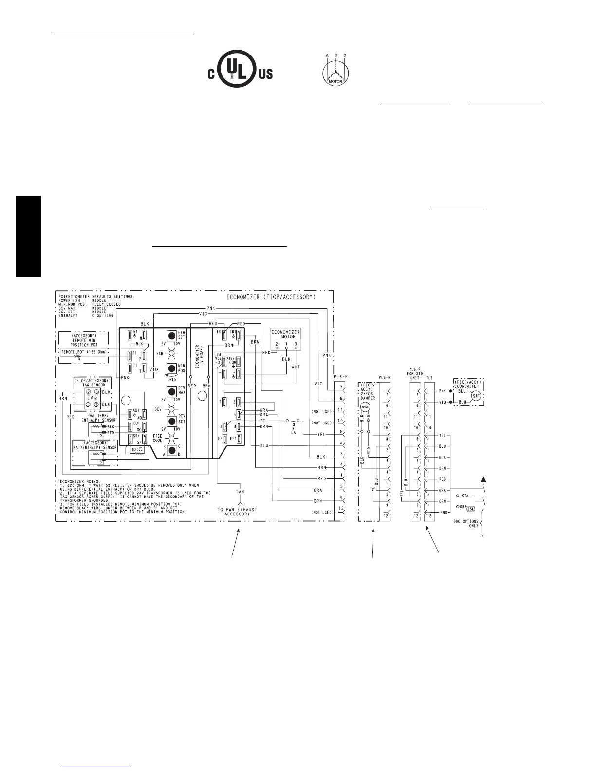
Economizer 2 Position Damper
Unit Without Economizer or
2 Position Damper
C08631
Fig. 65 -- EconoMi$ert IV Wiring
Step 11 — Adjust Factory-- Installed Options
Smoke Detectors —
Smoke detector(s) will be connected at the Central
Terminal Board (CTB), at terminals marked “Smoke
Shutdown”. Remove j umper JMP 3 when ready to
energize unit.
EconoMi$er IV Occupancy Switch —
Refer to Fig. 65 for general EconoMi$er IV wiring.
External occupanc y control is managed through a
connection on the Central Terminal Board.
If external occupancy control is desired, connect a time
clock or remotely controlled switch (closed for Occupied,
open for Unoccupied sequence) at terminals marked
OCCUPANCY on CTB. Remove or cut jumper JMP 2 to
complete the installation.
50TCQA

 Loading...


