7
A-B
0.5” (13)
B-C
1.0” (25)
A-C
1.0” (25)
MAXIMUM ALLOWABLE
DIFFERENCE IN. (MM)
C06110
Fig. 4 -- Unit Leveling Tolerances
Step 5 — Field Fabricate Ductwork
Cabinet return-air static pressure (a negative condition)
shall not exceed 0.35 in. wg (87 Pa) with economizer or
0.45 in. wg (112 Pa) without economizer.
For vertica l ducted appli cations, secure all ducts to roof
curb and building structure. Do not connect ductwork to
unit.
Insulate and weatherproof all e xternal ductwork, joints,
and roof openings with counter fl ashing and mastic in
accordance with applicable codes.
Ducts passing through unc onditioned spaces must be
insulated and cove red with a vapor barrier.
If a plenum return is used on a vertical unit, the return
should be ducted through the roof deck to comply with
applicable fire codes.
Fo r units with access ory electric heaters: Horizon tal
application s r equire a minimum clearance to combustib le
sur faces of 1--in (25 mm) fro m duct fo r firs t 12--in (305 mm)
away from unit. Vertical applications do not require a
minimum clearance.
Minimum clearance is not required around ductwork.
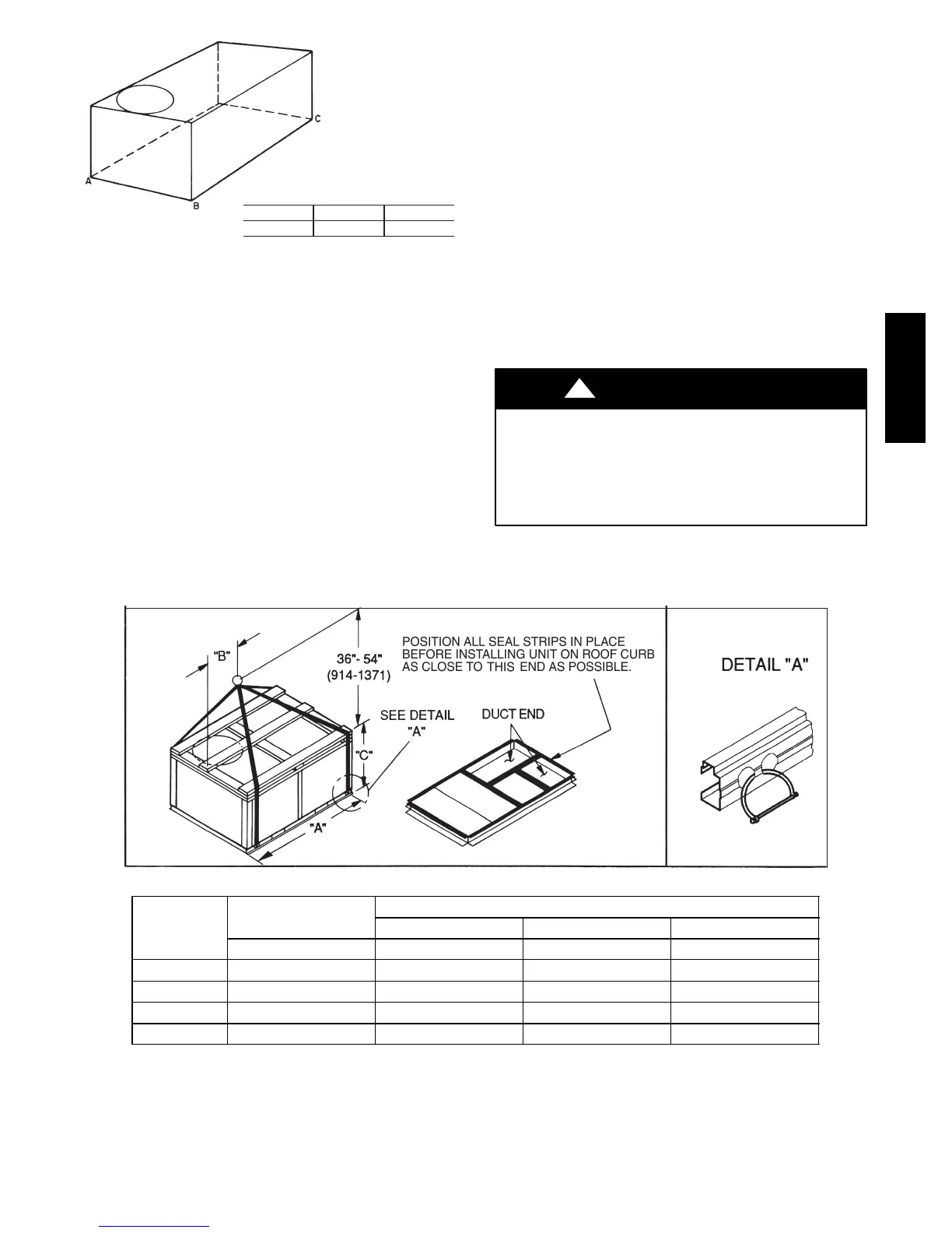
Step 6 — Rig and Place Unit
Keep unit upright and do not drop. Spreader bars are not
requir ed if top crating is left on unit. Rollers may be used to
move unit across a roof. Level by using unit frame as a
reference. See T able 1 and Fig. 5 for additional information.
Lifting holes are provided in ba se rails as shown in Fig. 5.
Refer to rigging instructions on unit.
UNIT DAMAGE HAZARD
Failure to follow this caution may result in
equipment damage.
All panels must be in place when rigging. Unit is not
designed for handling by fork truck.
CAUTION
!
Before setting the unit onto the curb, recheck gasketing on
curb.
C06005
UNIT
MAX WEIGHT
DIMENSIONS
A B C
LB KG IN MM IN MM IN MM
50TCQA04 755 343 74.38 1889 36.25 921 33.38 848
50TCQA05 760 345 74.38 1889 36.25 921 33.38 848
50TCQA06 840 381 74.38 1889 35.63 905 41.38 1051
50TCQA07 880 399 74.38 1889 37.25 946 41.38 1051
NOTES:
1. Dimensions in ( ) are in millimeters.
2. Hook rigging shackles through holes in base rail, as shown in detail “A.” Holes in base rails are centered around the
unit center of gravity. Use wooden top to prevent rigging straps from damaging unit.
Fig. 5 -- Rigging De tails
50TCQA

 Loading...


