Do you have a question about the Carrier 53KHET 30-36 and is the answer not in the manual?
Safety guidelines for installation and maintenance of air conditioning equipment.
Details on issues not covered by the manufacturer's warranty.
Specifies the operational temperature and wet bulb limits for cooling and heating.
Details the nominal voltage, minimum, and maximum voltage for the unit's power supply.
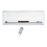
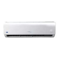
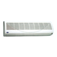
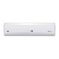
Guidelines on choosing the best location for the indoor unit based on clearances and airflow.
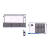
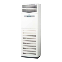
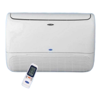
Specifies that the outdoor unit can be installed outdoors, on a wall, or on a roof.
Guidelines for selecting the outdoor unit location to avoid performance issues and ensure proper operation.
Details required clearances around the outdoor unit for airflow and access.
Specifies required clearances for multiple outdoor units installed in series.
Lists accessories included with the unit for domestic installation.
Lists additional accessories provided for export markets.
Lists accessories not supplied by the factory but required for installation.
Covers selecting the wall hole location, making the hole, and preparing the sleeve.
Details mounting the wall bracket, forming piping, and installing the unit onto the bracket.
Instructions on how to open the compartment, insert batteries, and close the cover.
Guidelines on operating the remote control, including distance and signal reception.
Instructions on how to fix the plastic holder for the remote control onto the wall.
Steps for unpacking, preparing, and assembling the wall support for the outdoor unit.
A visual chart outlining the key steps for connecting refrigerant piping.
Illustrates the four possible locations for refrigerant piping to exit the indoor unit.
Provides instructions and recommendations for connecting refrigerant piping to ensure performance.
Details pipe usage based on vertical distance and maximum lengths, and specifies pipe diameters.
Provides formulas and examples for calculating the correct refrigerant charge based on piping length.
Identifies and describes the ports and valves for refrigerant connections on the outdoor unit.
Illustrates the half unions for gas and liquid connections on the indoor unit.
Identifies the gas and liquid piping lines used for connections.
Lists and shows the necessary tools for preparing refrigerant piping.
Details removing protective caps from indoor and outdoor unit connections and mounting flare nuts.
Instructions for lubricating and tightening flare nuts to connect piping to indoor unit unions.
Instructions for connecting refrigerant piping to the flare valves of the outdoor unit.
Explains the importance of purging air and the procedure using refrigerant from the outdoor unit.
Details the procedure for purging air from the system using a vacuum pump.
Explains and details the process of pumping down refrigerant for re-installation or repair.
Describes methods like using soapy water to detect refrigerant leaks.
Explains the importance and method of insulating refrigerant lines for efficiency and condensation prevention.
Specifies the required inside diameter and material for the condensate drain line.
Shows the four possible paths for the condensate drain line from the indoor unit.
Provides instructions on how to properly install the drain line, avoiding traps and ensuring slope.
Covers voltage, kWh counter, distribution box, circuit breakers, and cable specifications.
Details electrical connections between indoor/outdoor units and the power supply, emphasizing safety.
Provides electrical data (Amps, Watts, Voltage) for different models and operating conditions.
Illustrates the terminal block and wiring connections for the outdoor unit.
Shows how to connect electrical cables to the indoor unit's terminal block.
Presents wiring diagrams, legends, wire sizes, and notes for field connections.
Reminds to check filters, panels, and connections before starting test operations.
Explains how to perform a cooling test run using the manual control button when ambient temps are low.
Details steps for cooling test run and provides tables for low pressure and total amps readings.
Details steps for heating test run and provides tables for high pressure and total amps readings.
Explains how air is supplied and drawn in, and the importance of unobstructed flow.
Details how to adjust air direction and use the swing function for model 30K.
Explains how to use the SWING button for automatic vertical louvre movement on model 36K.
Details how to set the horizontal supply air direction (left-right) using the SWING button.
Explains manual adjustment of vertical louvers to set horizontal airflow for model 30K.
Checks for proper bundling, sealing, test cycles, noise, and remote control operation.
Covers explaining unit operation, features, and providing manuals to the customer.
Explains the purpose of the self-diagnostic system for detecting and stopping malfunctions.
Lists common malfunctions, their reasons, and corresponding LED indicators for different models.
| Refrigerant | R-410A |
|---|---|
| Power Supply | 208-230V, 1 Phase, 60 Hz |
| Operating Range (Cooling) | 55°F - 125°F |
| Compressor Type | Scroll compressor |
| Coil Type | Aluminum Fin |
| Cooling Capacity | 30000-36000 BTU/h |