7
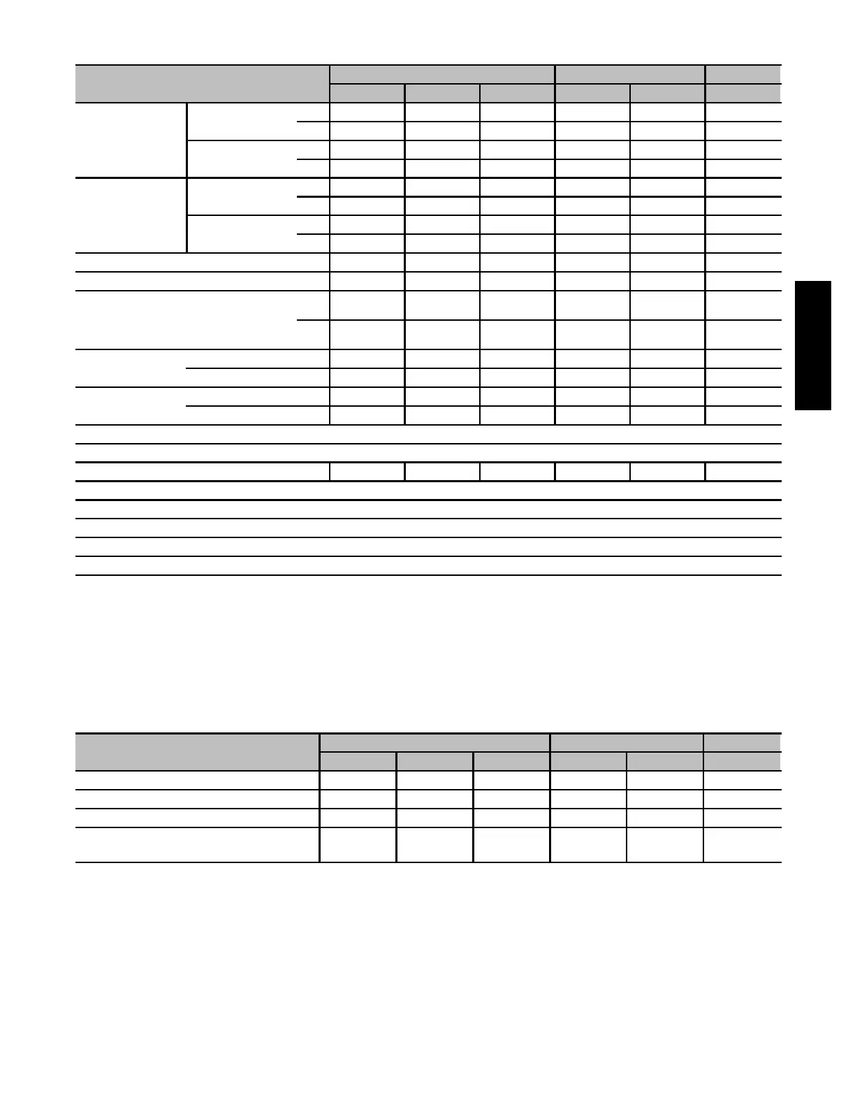
PHYSICAL DATA
UNIT SIZE
110 135 155
12 16 22 16 22 20
OUTPUT CAPACITY
BTUH*
(Nonweatherized
ICS) †
All 58CTA; 58CTX
Upflow
High 89,000 89,000 89,000 107,000 107,000 125,000
Low 59,000 59,000 59,000 70,000 70,000 82,000
All 58CTX Downflow/
Horizontal
High 85,000 85,000 85,000 102,000 102,000 119,000
Low 59,000 59,000 59,000 70,000 70,000 82,000
INPUT BTUH*
All 58CTA; 58CTX
Upflow
High 110,000 110,000 110,000 132,000 132,000 154,000
Low 72,500 72,500 72,500 87,000 87,000 101,500
All 58CTX Downflow/
Horizontal
HIgh 105,000 105,000 105,000 126,000 126,000 147,000
Low 72,500 72,500 72,500 87,000 87,000 101,500
AFUE † * Nonweatherized ICS 80.0 80.0 80.0 80.0 80.0 80.0
SHIPPING WEIGHT --- LB. (KG) 144 (65) 158 (72) 163 (74) 163 (74) 174 (79) 181 (82)
CERTIFIED TEMP RISE RANGE --- ° F (° C)
High 50---80
( 17 --- 3 3 )
40---70
( 17 --- 3 3 )
30---60
( 17 --- 3 3 )
50---80
( 17 --- 3 3 )
40---70
( 17 --- 3 3 )
45---75
( 17 --- 3 3 )
Low 30---60
( 17 --- 3 3 )
25---55
( 14 --- 3 0 )
20---50
( 11 --- 2 8 )
30---60
( 17 --- 3 3 )
25---55
( 14 --- 3 0 )
30---60
( 17 --- 3 3 )
CERTIFIED EXT
STA TIC PRESSURE
Heating 0.20 0.20 0.20 0.20 0.20 0.20
Cooling 0.50 0.50 0.80 0.50 0.50 0.50
AIRFLOW CFM‡
Heating High/Low 1335/1180 1290/1045 1555/1295 1525/1320 1865/1640 1790/1565
Cooling 1355 1695 2200 1710 2110 2230
LIMIT CONTROL SPST
HEATING BLOWER CONTROL Solid-State T ime Operation
BURNERS (Monoport) 5 5 5 6 6 7
GAS CONNECTION SIZE 1 / 2 --- i n . N PT
GAS VALVE (Redundant) Manufacturer White-Rodgers
Minimum Inlet Pressure (In. wc) 4.5 (Natura l Gas)
Maximum Inlet Pressure (In. wc) 13.6 (Natura l Gas)
IGNITION DEVICE Hot Surfa ce
* Gas input ratings are certified for elevations to 2000 ft. (610 M). For elevations above 2000 ft. (610 M), reduce ratings 4 percent for each 1000 ft. (305M)
above sea level. Refer to National Fuel Gas Code NFPA 54/ANSI Z223.1---2006 Table F.1 (d) or furnace Installation Instructions. In Canada, derate the unit
10 percent for elevations 2000 to 4500 ft. (610 to 1372 M) above sea level.
† Capacity in accordance with U.S. Government DOE test procedures.
‡ Airflow shown is f or bottom only return ---a ir supply. For air delivery above 1800 CFM, see Air Del ivery Table for other options. A filter is required f or each
return-air supply.
ICS — Isolated Combustion System
BLOWER PERFORMANCE DATA
UNIT SIZE
110 135 155
12 16 22 16 20 20
DIRECT-DRIVE MOTOR Hp (PSC) 1/3 1/2 3/4 1/2 3/4 3/4
MOTOR FULL LOAD AMPS 5.2 7.4 11.0 7.9 11.1 11.1
RPM (Nominal) – Speeds 1075-4 1075-5 1075-5 1075-4 1075-4 1075-5
BLOWER WHEEL DIAMETER × WIDTHS ---
In. (mm)
10 x 8
(254 X 203)
10 x 10
(254 X 254)
11 x 11
(279 x 279)
10 x 10
(254 x 254)
11 x 11
(279 x 279)
11 x 11
(279 x279)
PSC ---Permanent Split Capacitor
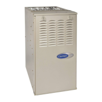
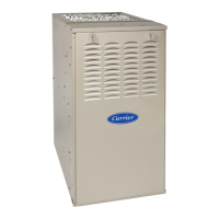
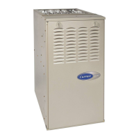
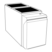
58CTA/CTX
 Loading...