21
Table 7 – Electrical Data
FURNACE
SIZE
V O LT S ---
H E R T Z ---
PHASE
OPERATING VOLTAGE
RANGE
MAX
UNIT
AMPS
UNIT
AMPACITY#
MAXIMUM
WIRE
LENGTH
FT. (M)‡
MAXIMUM
FUSE OR
CKT BKR
AMPS†
MINIMUM
WIRE
GAUGE
MAX* MIN.*
045--- 08/024045 1 1 5 --- 6 0 --- 1 127 104 5.3 7.42 49 (14.9) 15 14
045--- 12/036045 1 1 5 --- 6 0 --- 1 127 104 7.1 9.67 38 (11.5) 15 14
070--- 08/024070 1 1 5 --- 6 0 --- 1 127 104 5.2 7.22 51 (15.5) 15 14
070--- 12/036070 1 1 5 --- 6 0 --- 1 127 104 7.3 9.90 37 (11.2) 15 14
070--- 16/048070 1 1 5 --- 6 0 --- 1 127 104 10.1 13.42 27 (8.2) 15 14
090--- 14/042090 1 1 5 --- 6 0 --- 1 127 104 8.2 10.84 34 (10.3) 15 14
090--- 16/048090 1 1 5 --- 6 0 --- 1 127 104 9.9 13.0 28 (8.5) 15 14
090--- 20/060090 1 1 5 --- 6 0 --- 1 127 104 12.9 16.70 34 (10.3) 20 12
110--- 12/036110 1 1 5 --- 6 0 --- 1 127 104 8.2 10.76 34 (10.3) 15 14
110--- 16/048110 1 1 5 --- 6 0 --- 1 127 104 10.1 13.19 28 (8.5) 15 14
110--- 22/066110 1 1 5 --- 6 0 --- 1 127 104 13.7 17.60 32 (9.7) 20 12
135--- 16/048135 1 1 5 --- 6 0 --- 1 127 104 10.2 13.28 27 (8.2) 15 14
135--- 22/066135 1 1 5 --- 6 0 --- 1 127 104 14.5 18.61 30 (9.1) 20 12
155--- 20/060155 1 1 5 --- 6 0 --- 1 127 104 15.0 19.34 29 (8.8) 20 12
* Permissible limits of the voltage range at which the unit operates satisfactorily.
# Un it ampacity = 125% of largest operating component’s full load amps plu s 100% of all other potential operating components (EAC, humidifier,
etc.) full l oad amps.
{ Time---delay type is recommended.
} Length shown is as measured 1 way along wire path between unit and service panel for maximum 2% voltage drop.
U.S. Installations: Make all electrical connections in accordance
with National Electrical Code (NEC) ANSI/NFPA 70--2008 and
any local codes or ordinances that might apply.
FIRE HAZARD
Failure to follow this warning could result in personal
injury, death, or property damage.
Do not connect aluminum wire between disconnect switch
and furnace. Use only copper wire.
!
WARNING
Use a separate branch electrical circuit with a properly sized fuse
or circuit breaker for this furnace. See Table 7 for wire size and
fuse specifications. A readily accessible means of electrical
disconnect must be located within sight of the furnace.
NOTE: Proper polarity must be maintained for 115--v wiring. If
polarity is incorrect, control LED status indicator light will flash
rapidly and furnace will NOT operate.
J--BOX RELOCA
TION
NOTE: If factory location of J--Box is acceptable, go to next
section (ELECTRICAL CONNECTION TO J--BOX).
NOTE: On 14” wide casing models, the J--Box shall not be
relocated to other side of furnace casing when the vent pipe is
routed within the casing.
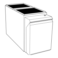
1. Remove and save two screws holding J--Box. (See Fig. 24
.)
NOTE: The J--Box cover need not be removed from the J--Box
in order to move the J--Box. Do NOT remove green ground
screw inside J--Box.
2. Cut wire tie on loop in furnace wires attached to J--Box.
3. Move J--Box to desired location.
4. Fasten J--Box to casing with the two screws removed in
Step 1.
5. Route J--Box wires within furnace away from sharp edges,
rotating parts, and hot surfaces.
Factory
Installed
Alternate
Location
A10291
Fig. 24 -- Relocating J--Box
ELECTRICAL CONNECTION TO
J--BOX
6. Reinstall cover to J--Box. Do not pinch wires between
cover and bracket.
Electrical Box on Furnace Casing Side. See Fig.
25.
FIRE OR ELECTRICAL SHOCK HAZARD
Failure to follow this warning could result in personal
injury, death, or property damage.
If field--supplied manual disconnect switch is to be mounted
on furnace casing side, select a location where a drill or
fastener cannot damage electrical or gas components.
!
WARNING
58CT