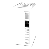
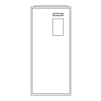
58MTA
Deluxe 4–Way Multipoise 2-Stage
Direct Vent Condensing Gas Furnace
Installation, Start-up, and Operating Instructions
Sizes 060-120, Series 120
NOTE: Read the entire instruction manual before starting the
installation.
This symbol → indicates a change since the last issue.
TABLE OF CONTENTS
SAFETY CONSIDERATIONS.....................................................2
INTRODUCTION..........................................................................2
CODES AND STANDARDS........................................................3
Safety.........................................................................................3
General Installation...................................................................3
Combustion and Ventilation Air ..............................................3
Duct Systems ............................................................................5
Acoustical Lining and Fibrous Glass Duct..............................5
Gas Piping and Gas Pipe Pressure Testing..............................5
Electrical Connections ..............................................................5
ELECTROSTATIC DISCHARGE (ESD) PRECAUTIONS........5
APPLICATIONS............................................................................6
General ......................................................................................6
Upflow Applications.................................................................6
Condensate Trap Location (Factory-Shipped
Orientation)..........................................................................6
Condensate Trap Tubing (Factory-Shipped
Orientation)..........................................................................6
Condensate Trap Location (Alternate Upflow
Orientation)..........................................................................7
Condensate Trap Tubing (Alternate Upflow
Orientation)..........................................................................7
Condensate Trap Field Drain Attachment..........................8
Pressure Switch Tubing.......................................................8
Upper Collector Box and Inducer Housing (Unused)
Drain Connections...............................................................8
Condensate Trap Freeze Protection ....................................8
Downflow Applications............................................................8
Condensate Trap Location ..................................................8
Condensate Trap Tubing.....................................................9
Condensate Trap Field Drain Attachment........................10
Pressure Switch Tubing.....................................................10
Condensate Trap Freeze Protection ..................................10
Horizontal Left (Supply-Air Discharge) Applications ..........10
Condensate Trap Location ................................................10
Condensate Trap Tubing...................................................10
Condensate Trap Field Drain Attachments ......................10
Pressure Switch Tubing.....................................................10
Condensate Trap Freeze Protection ..................................11
Construct a Working Platform..........................................11
Horizontal Right (Supply-Air Discharge) Applications ........11
Condensate Trap Location ................................................11
Condensate Trap Tubing...................................................13
Condensate Trap Field Drain Attachment........................13
Pressure Switch Tubing.....................................................13
Condensate Trap Freeze Protection ..................................13
Construct a Working Platform..........................................13
LOCATION..................................................................................13
General ....................................................................................13
Furnace Location Relative to Cooling
Equipment ...............................................................................14
Hazardous Locations...............................................................15
INSTALLATION.........................................................................15
Leveling Legs (If Desired).....................................................15
Installation in Upflow and Downflow
Applications ............................................................................15
Installation in Horizontal Applications ..................................17
Air Ducts.................................................................................17
General Requirements .......................................................17
Ductwork Acoustical Treatment .......................................17
Supply Air Connections ....................................................17
Return Air Connections.....................................................17
Filter Arrangement..................................................................18
Bottom Closure Panel.............................................................19
Gas Piping...............................................................................20
Electrical Connections ............................................................20
115-V Wiring.....................................................................22
24-V Wiring.......................................................................23
Accessories ........................................................................23
Direct Venting.........................................................................23
Removal of Existing Furnaces from Common Vent
Systems ..............................................................................23
Combustion-Air and Vent Piping .....................................25
Concentric Vent and Combustion-Air Termination
Kit Installation...................................................................30
Multiventing and Vent Terminations................................33
Condensate Drain....................................................................33
General...............................................................................33
Application.........................................................................34
Condensation Drain Protection .........................................34
START-UP ADJUSTMENT AND SAFETY CHECK ..............34
General ....................................................................................34
Prime Condensate Trap With Water......................................37
Purge Gas Lines......................................................................37
A93040
Visit www.carrier.com
Manufacturer reserves the right to discontinue, or change at any time, specifications or designs without notice and without incurring obligations.
Book 1 4
Tab 6a 8a
PC 101 Catalog No. 535–80129 Printed in U.S.A. Form 58MTA-7SI Pg 1 5-04 Replaces: 58MTA-6SI