(733mm)
(664mm) 28-7/8"
26-1/8"
(FLUE COLLAR)
g
5-15/16"
(135rnm)
(22ram)
7/8" DIA
ACCESSORY
33-5/16"
(846mm)
11/16"
(17ram)
(641mm)
25-1/4" --
22-9/16" _
(573mm)
JUNCTION BOX [_1
LOCATION
1/2" (13 mm) DIA.
THERMOSTAT WIRE ENTR_
ENTRY
7/8" (22mm) DtA.
ACCESSORY
- j
(549mm)
21-5/8"
BOTTOM INLET
24"
CASING
(610rnm)
24-7/8"
(632turn)
1/2
(140ram)
1-11/16"
(43ram)
A
D
--E
NOTES:
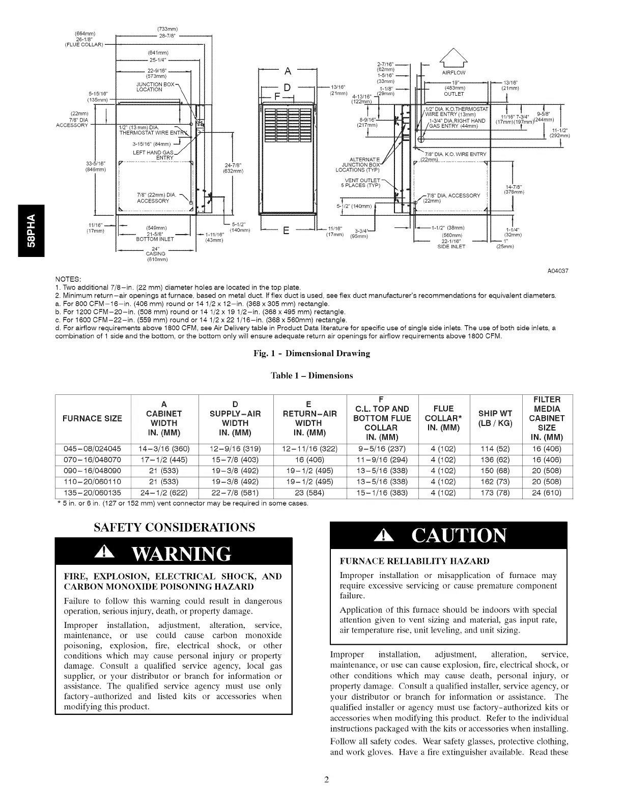
1. Two additional 7/8-in. (22 mm) diameter holes are located in the top plate.
(62ram)
(33mm)
(21ram)
LOCATIONS (TYP)
5 PLACES (TYP)
(483rnm)
ENTRY (13mm)
{g_mn_].........................................
(17rnm) (95turn) (560ram)
l
14-7/8"
(378mrn)
t
1-1/4"
(32ram)
SIDE INLET (25ram)
A04037
2. Minimum return-air openings at furnace, based on metal duct. If flex duct is used, see flex duct manufacturer's recommendations for equivalent diameters.
a. For 800 CFM-16-in. (406 ram) round or 14 1/2 x 12-in. (368 x 305 ram) rectangle.
b. For 1200 CFM-20-in. (508 ram) round or 14 1/2 x 19 1/2-in. (368 x 495 ram) rectangle.
c. For 1600 CFM-22-in. (559 ram) round or 14 1/2 x 22 1/16-in. (368 x 560mm) rectangle.
d. For airflow requirements above 1800 CFM, see Air Delivery table in Product Data literature for specific use of single side inlets. The use of both side inlets, a
combination of 1 side and the bottom, or the bottom only will ensure adequate return air openings for airflow requirements above 1800 CFM.
Fig. 1 - Dimensional Drawing
Table 1 - Dimensions
F FILTER
A D E
C,L, TOP AND FLUE MEDIA
CABINET SUPPLY-AIR RETURN-AIR SHIP WT
FURNACE SIZE BOTTOM FLUE COLLAR* CABINET
WIDTH WIDTH WIDTH COLLAR IN. (MM) (LB / KG) SIZE
IN. (MM) IN. (MM) IN. (MM) IN. (MM) IN. (MM)
045-08/024045 14-3/16 (360) 12-9/16 (319) 12-11/16 (322) 9-5/16 (237) 4 (102) 114 (52) 16 (406)
070-16/048070 17-1/2 (445) 15-7/8 (403) 16 (406) 11-9/16 (294) 4 (102) 136 (62) 16 (406)
090-16/048090 21 (533) 19-3/8 (492) 19-1/2 (495) 13-5/16 (338) 4 (102) 150 (68) 20 (508)
110-20/060110 21 (533) 19-3/8 (492) 19-1/2 (495) 13-5/16 (338) 4 (102) 162 (73) 20 (508)
135-20/060135 24-1/2 (622) 22-7/8 (581) 23 (584) 15-1/16 (383) 4 (102) 173 (78) 24 (610)
5 in. or 6 in. (127 or 152 mm) vent connector may be required in some cases.
SAFETY CONSIDERATIONS
FIRE, EXPLOSION, ELECTRICAL SHOCK, AND
CARBON MONOXIDE POISONING HAZARD
Failure to follow this warning could result in dangerous
operation, serious injury, death, or property damage.
Improper installation, adjustment, alteration, service,
maintenance, or use could cause carbon monoxide
poisoning, explosion, fire, electrical shock, or other
conditions which may cause personal injury or property
damage. Consult a qualified service agency, local gas
supplier, or your distributor or branch for information or
assistance. The qualified service agency nmst use only
factory-authorized and listed kits or accessories when
modifying this product.
FURNACE RELIABILITY HAZARD
Improper installation or nfisapplication of furnace may
require excessive servicing or cause premature component
failure.
Application of this furnace should be indoors with special
attention given to vent sizing and material, gas input rate,
air temperature rise, unit leveling, and unit sizing.
Improper installation, adjustment, alteration, service,
maintenance, or use can cause explosion, fire, electrical shock, or
other conditions which may cause death, personal iniury, or
property damage. Consult a qualified installer, service agency, or
your distributor or branch for information or assistance. The
qualified installer or agency must use factory-authorized kits or
accessories when modifying this product. Refer to the individual
instructions packaged with the kits or accessories when installing.
Follow all safety codes. Wear safety glasses, protective clothing,
and work gloves. Have a fire extinguisher available. Read these