g
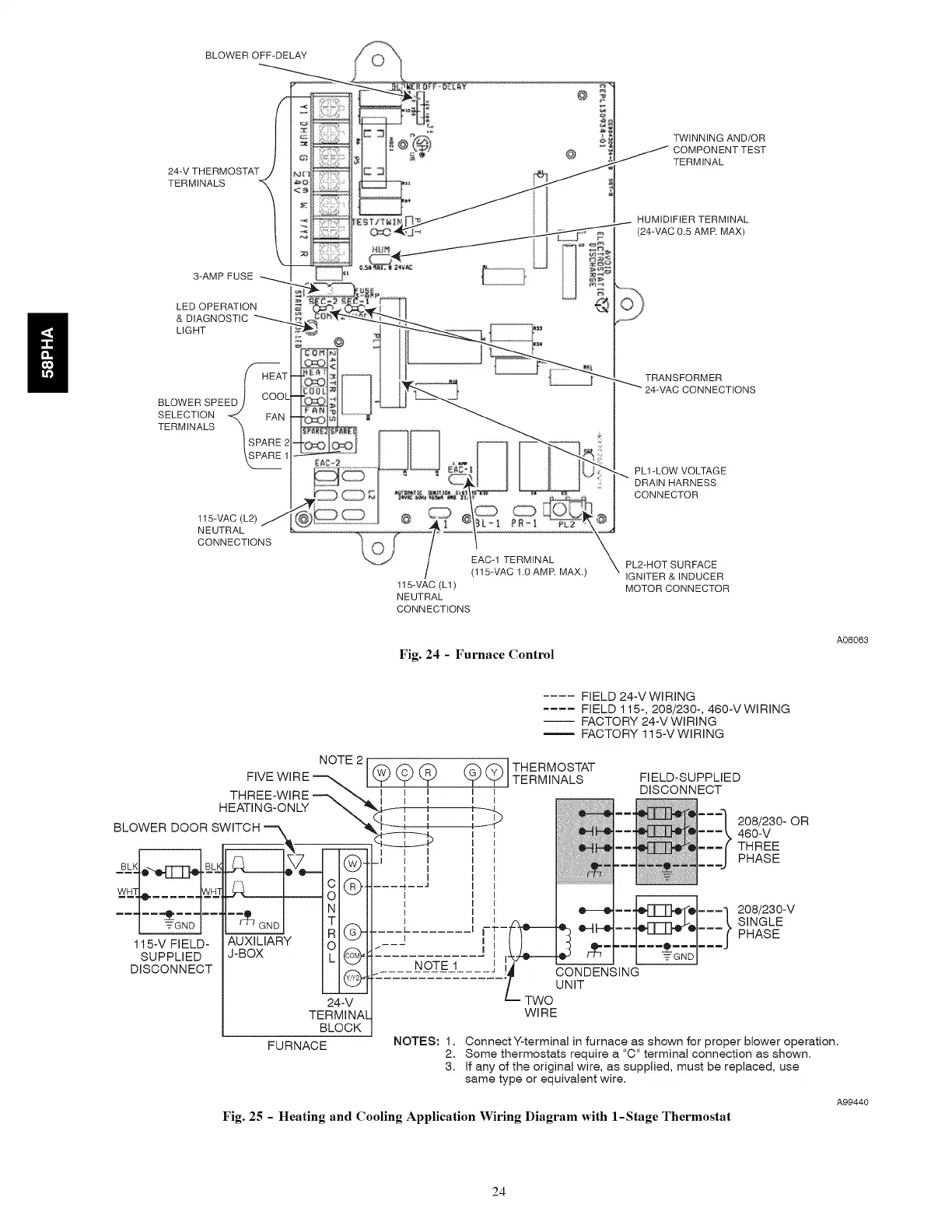
BLOWER OFF-DELAY
24-V THERMOSTAT j
TERMINALS
3-AMPFUSE
LED OPERATION
& DIAGNOSTIC
LIGHT
BLOWER SPEED
SELECTION
TERMINALS
TWINNING AND/OR
J OMPONENT TEST
TERMINAL
HUMIDIFIER TERMINAL
(24-VAC 0.5 AMR MAX)
TRANSFORMER
CONNECTIONS
115-VAC (L2)
NEUTRAL
CONNECTIONS
EAC-1 TERMINAL
(115-VAC 1.0 AMR MAX.)
115-VAC (L1)
NEUTRAL
CONNECTIONS
Fig. 24 - Furnace Control
PL1-LOW VOLTAGE
DRAIN HARNESS
CONNECTOR
PL2-HOT SURFACE
IGNITER & INDUCER
MOTOR CONNECTOR
A08063
.... FIELD 24-V WIRING
.... FIELD 115-, 208/230-, 460-VWIRING
-- FACTORY 24-VWIRING
FACTORY 115-V WIRING
TERMINAL
BLOCK
FURNACE
NOTES: 1.
2.
3.
ConnectY-terminal in furnace as shown for proper blower operation.
Some thermostats require a "C" terminal connection as shown.
If any of the original wire, as supplied, must be replaced, use
same type or equivalent wire.
A99440
Fig. 25 - Heating and Cooling Application Wiring Diagram with 1-Stage Thermostat
24
 Loading...