B
S1
S2
SPLICE
BOX
YEL
WHT
See notes 7 and 11
O/W2
HEAT STAGE 2
N/A
Y1
COOL/HEAT
STAGE 1
OUTDOOR
SENSOR
CONNECTION
HEATER
CONTROL BOX
GRN
ORN
BRN
BRN
RED
24 VAC HOT
24 VAC COMM
HEAT STAGE 3
COOL/HEAT
STAGE 2
FAN
C
R
G
W/W1
Y/Y2
MODEL 2S
THERMOSTAT
A97138
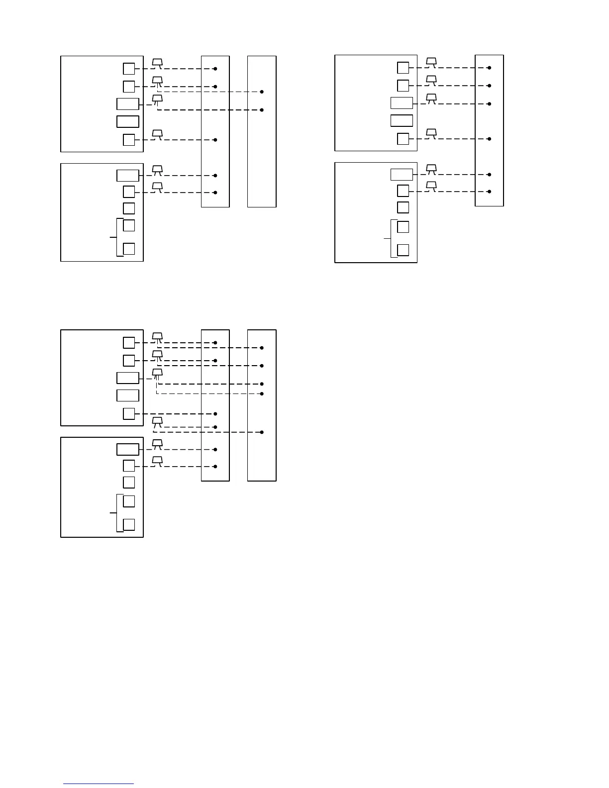
→Fig. 22—Single-Speed Packaged Heat Pump
with Single-Stage Electric Heat (50HS, HX, ZH)
B
S1
S2
SPLICE
BOX
YEL
WHT
O/W2
HEAT STAGE 2
N/A
Y1
COOL/HEAT
STAGE 1
OUTDOOR
SENSOR
CONNECTION
HEATER
CONTROL BOX
ORN
VIO
BRN
BRN
RED
RED
24 VAC HOT
24 VAC COMM
HEAT STAGE 3
COOL/HEAT
STAGE 2
FAN
C
R
G
W/W1
Y/Y2
MODEL 2S
THERMOSTAT
PNK
RED (TRAN)
See notes 7, 8, and 11
A97139
→Fig. 23—Single-Speed Packaged Heat Pump
with 2-Stage Electric Heat (50HS, HX, ZH)
B
S1
S2
SPLICE
BOX
WHT
YEL
O/W2
HEAT STAGE 2
N/A
Y1
COOL/HEAT
STAGE 1
OUTDOOR
SENSOR
CONNECTION
GRN
ORN
BRN
RED
24 VAC HOT
24 VAC COMM
HEAT STAGE 3
COOL/HEAT
STAGE 2
FAN
C
R
G
W/W1
Y/Y2
MODEL 2S
THERMOSTAT
See notes 7 and 11
A97140
→Fig. 24—Single-Speed Packaged Heat Pump
with Single-Stage Gas Furnace (48HX)
→WIRING DIAGRAM NOTES:
1. Furnace must control second-stage heat.
2. Cut jumper R19 to convert thermostat to AC operation.
3. O/W2 can control second-stage heat. Refer to indoor equip-
ment Installation Instructions for proper setup.
4. Refer to outdoor unit Installation Instructions for latent kit
requirements.
5. Terminals marked with * may not be present on equipment.
6. O/W2 energizes reversing valve in cooling.
7. Refer to outdoor equipment Installation Instructions for proper
setup.
8. Omit red and pink wires from diagram when wiring a 50ZP,
ZH with 2-stage heaters.
9. Select the "ZONE" position on the 2-speed heat pump control
board.
10. Refer to fan coil Installation Instructions for proper wiring.
11. Program thermostat to bring on G (fan) with any W (heat)
selection. See Step 4, item 5 under thermostat configuration.
9