2
CONTENTS (cont)
Page
• LEAD/LAG DETERMINATION
• CAPACITY SEQUENCE DETERMINATION
• CAPACITY CONTROL OVERRIDES
Head Pressure Control
. . . . . . . . . . . . . . . . . . . . . . . . . . 27
• COMFORTLINK™ UNITS (With EXV)
• UNITS WITH TXV
Pumpout
. . . . . . . . . . . . . . . . . . . . . . . . . . . . . . . . . . . . . . . . 27
• EXV UNITS
• TXV UNITS
Marquee Display Usage
. . . . . . . . . . . . . . . . . . . . . . . . . 29
Service Test
. . . . . . . . . . . . . . . . . . . . . . . . . . . . . . . . . . . . . 29
Configuring and Operating Dual Chiller
Control
. . . . . . . . . . . . . . . . . . . . . . . . . . . . . . . . . . . . . . . . 29
Temperature Reset
. . . . . . . . . . . . . . . . . . . . . . . . . . . . . . 43
Cooling Set Point (4 to 20 mA)
. . . . . . . . . . . . . . . . . . . 45
Demand Limit
. . . . . . . . . . . . . . . . . . . . . . . . . . . . . . . . . . . 46
• DEMAND LIMIT (2-Stage Switch Controlled)
• EXTERNALLY POWERED DEMAND LIMIT
(4 to 20 mA Controlled)
• DEMAND LIMIT (CCN Loadshed Controlled)
TROUBLESHOOTING
. . . . . . . . . . . . . . . . . . . . . . . . . 47-52
Compressor Protection Control System
(CPCS) Board
. . . . . . . . . . . . . . . . . . . . . . . . . . . . . . . . . 47
Compressor Ground Current (CGF) Board
(30GTN,R and 30GUN,R130-210, 230A-315A,
and 330A/B-420A/B)
. . . . . . . . . . . . . . . . . . . . . . . . . . . 47
EXV Troubleshooting
. . . . . . . . . . . . . . . . . . . . . . . . . . . . 47
• STEP 1 — CHECK PROCESSOR EXV OUTPUTS
• STEP 2 — CHECK EXV WIRING
• STEP 3 — CHECK RESISTANCE OF EXV MOTOR
WINDINGS
• STEP 4 — CHECK THERMISTORS THAT
CONTROL EXV
• STEP 5 — CHECK OPERATION OF THE EXV
Alarms and Alerts
. . . . . . . . . . . . . . . . . . . . . . . . . . . . . . . 48
SERVICE
. . . . . . . . . . . . . . . . . . . . . . . . . . . . . . . . . . . . . 53-65
Electronic Components
. . . . . . . . . . . . . . . . . . . . . . . . . 53
Compressors
. . . . . . . . . . . . . . . . . . . . . . . . . . . . . . . . . . . . 53
• COMPRESSOR REMOVAL
• OIL CHARGE
Cooler
. . . . . . . . . . . . . . . . . . . . . . . . . . . . . . . . . . . . . . . . . . . 53
•COOLER REMOVAL
• REPLACING COOLER
• SERVICING THE COOLER
Condenser Coils
. . . . . . . . . . . . . . . . . . . . . . . . . . . . . . . . 56
Condenser Fans
. . . . . . . . . . . . . . . . . . . . . . . . . . . . . . . . . 57
Refrigerant Feed Components
. . . . . . . . . . . . . . . . . . . 58
• ELECTRONIC EXPANSION VALVE (EXV)
• MOISTURE-LIQUID INDICATOR
• FILTER DRIER
• LIQUID LINE SOLENOID VALVE
• LIQUID LINE SERVICE VALVE
Thermistors
. . . . . . . . . . . . . . . . . . . . . . . . . . . . . . . . . . . . . 59
•LOCATION
• REPLACING THERMISTOR T2
• REPLACING THERMISTORS T1,T5,T6,T7, AND T8
• THERMISTORS T3 AND T4
• THERMISTOR/TEMPERATURE SENSOR CHECK
Page
Safety Devices
. . . . . . . . . . . . . . . . . . . . . . . . . . . . . . . . . . 64
• COMPRESSOR PROTECTION
• LOW OIL PRESSURE PROTECTION
• CRANKCASE HEATERS
• COOLER PROTECTION
Relief Devices
. . . . . . . . . . . . . . . . . . . . . . . . . . . . . . . . . . . 65
• HIGH-SIDE PROTECTION
• LOW-SIDE PROTECTION
• PRESSURE RELIEF VALVES
Other Safeties
. . . . . . . . . . . . . . . . . . . . . . . . . . . . . . . . . . . 65
PRE-START-UP
. . . . . . . . . . . . . . . . . . . . . . . . . . . . . . . . . . 65
System Check
. . . . . . . . . . . . . . . . . . . . . . . . . . . . . . . . . . . 65
START-UP AND OPERATION
. . . . . . . . . . . . . . . . . . 66,67
Actual Start-Up
. . . . . . . . . . . . . . . . . . . . . . . . . . . . . . . . . . 66
Operating Limitations
. . . . . . . . . . . . . . . . . . . . . . . . . . . 66
• TEMPERATURES
• VOLTAGE
• MINIMUM FLUID LOOP VOLUME
• FLOW RATE REQUIREMENTS
Operation Sequence
. . . . . . . . . . . . . . . . . . . . . . . . . . . . . 67
Refrigerant Circuit
. . . . . . . . . . . . . . . . . . . . . . . . . . . . . . . 67
FIELD WIRING
. . . . . . . . . . . . . . . . . . . . . . . . . . . . . . . . 67-70
APPENDIX A — CCN TABLES
. . . . . . . . . . . . . . . . 71-79
APPENDIX B — FLUID PRESSURE DROP
CURVES
. . . . . . . . . . . . . . . . . . . . . . . . . . . . . . . . . . . . 80-87
START-UP CHECKLIST
. . . . . . . . . . . . . . . . .CL-1 to CL-8
GENERAL
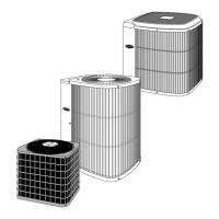
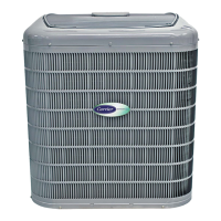
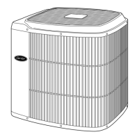
The model 30GTN,R chillers are air-cooled chillers utiliz-
ing refrigerant R-22. The model 30GUN,R chillers are air-
cooled chillers utilizing refrigerant R-134a.
Unit sizes 230-420 are modular units which are shipped as
separate sections (modules A and B). Installation instructions
specific to these units are shipped inside the individual mod-
ules. See Tables 1A and 1B for a listing of unit sizes and modu-
lar combinations. For modules 230B-315B, follow all general
instructions as noted for unit sizes 080-110. For all remaining
modules, follow instructions for unit sizes 130-210.
INTRODUCTION
This publication contains Start-Up, Service, Controls, Oper-
ation, and Troubleshooting information for the 30GTN,R040-
420 and 30GUN,R040-420 liquid chillers with ComfortLink
controls.
The 30GTN,R and 30GUN,R040-420 chillers are equipped
with electronic expansion valves (EXVs) or, on size 040-110
FIOP (factory-installed option) units, conventional thermostat-
ic expansion valves (TXVs). The size 040-110 FIOP chillers
are also equipped with liquid line solenoid valves (LLSV).
NOTE: TXVs are not available on modular units.
Differences in operations and controls between standard
and 040-110 FIOP units are noted in appropriate sections in
this publication. Refer to the Installation Instructions and the
Wiring Diagrams for the appropriate unit for further details.
 Loading...