34
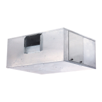
System Fan Coil Unit
HVAC Guide Specifications
Size Range: 600 to 4000 Nominal Cfm
Carrier Model Numbers:
42BHE (Horizontal Fan Coil Unit)
42BVE (Vertical Fan Coil Unit)
Part 1 — General
1.01 SYSTEM DESCRIPTION
Horizontal and vertical, 2-pipe or 4-pipe, belt-
driven, galvanized casing model fan coil unit for
ducted installation above the ceiling or within
floor-mounted cabinet, with full access to internal
components.
1.02 QUALITY ASSURANCE
A. Unit shall be constructed in accordance with ETL
and ETL, Canada standards. Units comply with the
minimum requirements of the US and Canadian
national product safety standard, UL 1995/CSA
C22.2 No. 236. Factory-installed motors and elec-
tric heaters shall be UL approved. Insulation and
adhesive shall meet NFPA-90A requirements for
flame spread and smoke generation.
B. Coils shall be tested in accordance with AHRI stan-
dard 410, latest edition. Each coil shall be factory
tested for leakage at 300-psig air pressure with coil
submerged in water.
1.03 DELIVERY, STORAGE AND HANDLING
Unit shall be handled and stored in accordance with
the manufacturer’s instructions.
Part 2 — Products
2.01 EQUIPMENT
A. General:
Factory-assembled, horizontal and vertical, draw-
thru type fan coil unit for ducted installation above
the ceiling or floor mounting. Unit shall be complete
with water coils, fan(s), motor, belt drive, drain pan,
and filter.
B. Casing:
Construction shall be heavy-gage galvanized steel,
lined with one-in. thick fiberglass Tuf-Skin™ II
thermal/acoustical insulation. Knockouts shall be
provided for hanging the horizontal unit, that will
accept
3
/
8
-in. threaded rod at the top and bottom of
all unit corners. Supply and return duct connections
shall be 1 in. long. Removable side panels shall be
provided for access to the fan/motor assembly.
Access panels shall be easily removable with hex key
tool on vertical unit, and without tools on horizontal
unit. A double-sloped drain pan shall be constructed
of stainless steel, extending under the full length and
width of the coil(s) with a
3
/
4
-in. male nominal pipe
thread stainless steel drain connection and
1
/
2
-in.
male NPT stainless secondary drain connection (cap
when not required). The outside surface of the drain
pan shall be insulated with
1
/
8
-in. closed cell
insulation. Drain pan is removable from cabinet
from same end as coil connections for ease of
cleaning.
C. Fans:
Belt-driven, double-width fan wheels shall have for-
ward-curved blades and be statically and dynamically
balanced. Fan drive shall consist of variable-pitch
motor pulley, fixed-diameter blower sheave with
keyed shaft, and V-belt. Fan drive shall be designed
for 120% of rated fan horsepower. Fans and scrolls
shall be of galvanized steel. Bearings are ball bear-
ings, permanently lubricated and sealed for life.
Bearings are isolated from the blower housing by
rubber mounts set into heavy gage metal support
system. The blower housing shall be isolated from
the cabinet and motor.
D. Coils:
Standard unit shall be equipped with a 4-row coil for
installation in a 2-pipe system and additional rows of
coil shall be provided as an option for installation in
a 4-pipe system. Coils shall have
1
/
2
-in. copper
tubes, aluminum fins bonded to the tubes by
mechanical expansion and have a working pressure
of 250 psig at 200 F. Each coil shall have a manual
air vent and sweat connections for copper tubes.
E. Operating Characteristics:
A single-circuit coil unit installed in a 2-pipe system
shall be capable of providing heating or cooling as
determined by the operating mode of the central
water supply system. A double-circuit coil unit
installed in a 4-pipe system shall be capable of pro-
viding sequenced heating and cooling.
F. Motor(s):
1. Fan motors shall be open, drip-proof, single-
speed, single or 3 phase, suitable for continu-
ous duty at 104 F (40 C). Single-phase motors
are capacitor start, include automatic reset ther-
mal overload protection and are available in
115, 208, 230, or 277 volts (60 Hz) or 220
volts (50 Hz). Three-phase motors are available
in 208, 230, or 460 volts (60 Hz) or 380 volts
(50 Hz).
2. Motors are Class B, continuous duty rated.
Motors are resilient mounted (
1
/
4
to 2 hp), rigid
base mounted (3 and 5 hp), NEMA frame
motors. Motors are factory wired to unit junc-
tion or control box. Motor bearings are perma-
nently lubricated. Motors are mounted on an
adjustable base for belt tensioning and align-
ment. The motor and drive are installed on the
same end as the coil connection for ease of
service.
G. Special Features:
1. Coils:
a. Unit coil(s) shall be equipped with automatic
air vent(s).
b. Unit shall be equipped with a high-capacity
6-row or 8-row coil for installation in a
2-pipe system.
Guide specifications
 Loading...