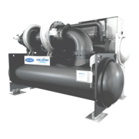
Fig. 25 — 19DV Chiller with VFD
LEGEND
1—Disconnect
2—Chilled Water Pump Starter
3—Condenser Water Pump Starter
4—Cooling Tower Fan Starter
(Low Fan, High Fan)
5—Vents
6—HMI (hidden)
7—Unit-Mounted VFD
8—Control Panel
9—Strainers
10 — Chilled Water Pump
11 — Condenser Water Pump
12 — Pressure Gages
Piping
Control Wiring
Power Wiring
NOTES:
1. Wiring and piping shown are for general point-of-connection only and are not
intended to show details for a specific installation. Certified field wiring and
dimensional diagrams are available on request.
2. All wiring must comply with applicable codes.
3. Wiring not shown for optional devices such as:
• Remote Start/Stop
• Remote Alarms
• Optional Safety Device
• 4 to 20 mA Resets
• Optional Remote Sensors
4. IMPORTANT: Carrier suggests that a structural engineer be consulted if trans-
mission of vibrations from mechanical equipment is of concern.
5. Isolation valves are recommended on the evaporator and condenser water pip-
ing to each chiller for service.
6. Operating environment — Chiller should be installed in an indoor environment
where the ambient temperature is 40 to 104°F (4 to 40°C) with a relative
humidity (non-condensing) of 95% or less. To ensure that electrical compo-
nents operate properly, do not locate the chiller in an area exposed to dust, dirt,
corrosive fumes, or excessive heat and humidity.
7. Be sure to pipe
3
/
8
-in. VFD condensate pipe to drain.
NO. OF CONDUCTORS CONDUCTOR RANGE GROUND CONNECTOR

 Loading...


