9
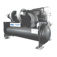
Table 1 — 19DV Dimensions (Nozzle-In-Head Waterbox)
NOTES:
1. Service access should be provided per American Society of Heat-
ing, Refrigerating, and Air-Conditioning Engineers (ASHRAE) 15,
latest edition, National Fire Protection Association (NFPA) 70, local
safety code, and Carrier drawings.
2. Overhead clearance for service rigging compressor should be at
minimum 3 feet (914 mm) with 5 feet recommended for easier over-
head access.
3. Dimensions are approximate. Certified drawings available upon
request.
4. Marine waterboxes typically add to the width of the machine. See
certified drawings for details.
5. ‘A’ length dimensions shown are for standard 150 psig (1034 kPa)
design and flanged connections. See certified drawings.
6. 19DV unit heights can vary depending on the configuration. Check
19DV certified drawings for height information.
7. Table contains heat exchanger dimensions. For arrangements
where the compressor motor housing extends past the waterbox,
consult the 19DV certified drawings.
8. Consult factory for configurations not listed in the above table.
Table 2 — 19DV Nozzle Size
Table 3 — 19DV Dimensions (Marine Waterbox, 150 psig)
NOTES:
1. Service access should be provided per American Society of Heat-
ing, Refrigerating, and Air-Conditioning Engineers (ASHRAE) 15,
latest edition, National Fire Protection Association (NFPA) 70, local
safety code, and Carrier drawings.
2. Overhead clearance for service rigging compressor should be at
minimum 3 feet (914 mm) with 5 feet recommended for easier over-
head access.
3. Dimensions are approximate. Certified drawings available upon
request.
4. Marine waterboxes typically add to the width of the machine. See
certified drawings for details.
5. 19DV unit height can vary depending on the configuration. Check
19DV certified drawings for height information.
6. The table does not take into account equipment overhang or nozzle
configurations with nozzles on opposite ends of chiller or mix of
waterbox types. See certified drawings for final unit dimensions.
HEAT EXCHANGER SIZE PASSES
A (LENGTH, WITH
NOZZLE-IN-HEAD
WATERBOX)
B (WIDTH) C (HEIGHT)
in. mm in. mm in. mm
G2*
1 pass 189.0 4801
108.4 2753 117.0 29722 pass 180.9 4595
3 pass 185.5 4712
G4*
1 pass 209.5 5322
99.9 2537 117.0 29722 pass 201.4 5116
3 pass 206.0 5233
H2*
1 pass 190.8 4847
114.0 2896 123.9 31482 pass 183.4 4659
3 pass 187.5 4763
H4*
1 pass 211.3 5368
110.3 2802 123.9 31482 pass 203.9 5180
3 pass 208.0 5284
HEAT
EXCHANGER
FRAME SIZE
NOZZLE SIZE (in.)
(Nominal Pipe Size)
Evaporator Condenser
1-Pass 2-Pass 3-Pass 1-Pass 2-Pass 3-Pass
G 14 14 12 12 10 10
H 14 14 12 12 12 10
HEAT EXCHANGER SIZE PASSES
A (LENGTH, WITH MARINE
WATERBOX)
B (WIDTH) C (HEIGHT)
in. mm in. mm in. mm
G2*
1 pass 218.5 5550
108.4 2753 117.0 29722 pass 192.3 4883
3 pass 210.8 5353
G4*
1 pass 239.0 6071
102.2 2594 117.0 29722 pass 212.8 5404
3 pass 231.3 5871
H2*
1 pass 220.5 5601
114.0 2896 123.9 31482 pass 194.2 4933
3 pass 212.5 5215
H4*
1 pass 241.0 6122
112.9 2868 123.9 31482 pass 214.7 5454
3 pass 233.0 5919

 Loading...


