Manufacturer reserves the right to discontinue, or change at any time, specifications or designs without notice and without incurring obligations.
Catalog No. 04-53190041-01 Printed in U.S.A. Form 19XR-CLT-3T Pg 1 11-16 Replaces: 19XR-CLT-2T
Controls Operation and Troubleshooting
CONTENTS
Page
SAFETY CONSIDERATIONS. . . . . . . . . . . . . . . . . . . . .1,2
GENERAL . . . . . . . . . . . . . . . . . . . . . . . . . . . . . . . . . . . . . . . . 2
Abbreviations Used in This Manual . . . . . . . . . . . . . . 2
HARDWARE . . . . . . . . . . . . . . . . . . . . . . . . . . . . . . . . . . 2-12
Main Control Board . . . . . . . . . . . . . . . . . . . . . . . . . . . . . . 2
ISM (Integrated Starter Module) . . . . . . . . . . . . . . . . . . 2
IOB (Input/Output Board). . . . . . . . . . . . . . . . . . . . . . . . . 3
Communication Cables . . . . . . . . . . . . . . . . . . . . . . . . . . 3
Sensors . . . . . . . . . . . . . . . . . . . . . . . . . . . . . . . . . . . . . . . . . 12
• PRESSURE TRANSDUCERS
• TEMPERATURE SENSORS
Controls Outputs. . . . . . . . . . . . . . . . . . . . . . . . . . . . . . . . 12
• EVAPORATOR/CONDENSER WATER PUMP
• INLET GUIDE VANE
• ECONOMIZER DAMPER VALVE
• ENVELOP CONTROL/HGBP VALVE
•VFD
PIC 5 USER INTERFACE. . . . . . . . . . . . . . . . . . . . . . 12-17
Web Connection . . . . . . . . . . . . . . . . . . . . . . . . . . . . . . . . 12
General Interface Features . . . . . . . . . . . . . . . . . . . . . . 13
•ICONS
• SCREENS
PIC 5 CONTROL OPERATION . . . . . . . . . . . . . . . . 17-31
Start-Stop Control. . . . . . . . . . . . . . . . . . . . . . . . . . . . . . . 17
•LOCAL
• LOCAL SCHEDULE
•REMOTE
•NETWORK
Compressor Run Status. . . . . . . . . . . . . . . . . . . . . . . . . 17
Chiller Start-Up Sequence . . . . . . . . . . . . . . . . . . . . . . . 18
• PRE-START CHECK
•START-UP
Chiller Shutdown Sequence . . . . . . . . . . . . . . . . . . . . . 19
Oil Lubrication Control. . . . . . . . . . . . . . . . . . . . . . . . . . 19
Control Points. . . . . . . . . . . . . . . . . . . . . . . . . . . . . . . . . . . 19
• SET POINT
• CONTROL POINT TEMPERATURE
• TEMPERATURE RESET
• CAPACITY CONTROL
• RAMP LOADING
• SURGE CORRECTION CONTROL
• ENVELOP/HOT GAS BYPASS (HGBP) CONTROL
• ECONOMIZER DAMPER VALVE CONTROL
• DEMAND LIMIT
• OVERRIDE CONTROL
• RECYCLE CONTROL
• RUNNING TIMERS AND COUNTERS
• WATER PUMPS CONTROL (FREEZE
PREVENTION)
• CONTROL TEST
•SWIFT RESTART
• COOLING TOWER CONTROL
Page
• HEAD PRESSURE CONTROL
• ICE BUILD OPTION
•TIME SCHEDULE
• BLACK BOX
• PRESSURE TRANSDUCER CALIBRATION
• TEMPERATURE SENSOR CALIBRATION
• ISM VFD INPUT/OUTPUT CALIBRATION
• ALARM EMAIL
• PROGNOSTICS
• MASTER SLAVE CONTROL
Oil EXV Option . . . . . . . . . . . . . . . . . . . . . . . . . . . . . . . . . . 30
Pumpdown/Lockout. . . . . . . . . . . . . . . . . . . . . . . . . . . . . 30
Displaying Data Trends . . . . . . . . . . . . . . . . . . . . . . . . . 30
Hydraulic Option . . . . . . . . . . . . . . . . . . . . . . . . . . . . . . . . 31
• WATER FLOW MEASUREMENT
• WATER PRESSURE DIFFERENCE MEASUREMENT
• MARINE OPTION(S)
DIAGNOSTICS AND TROUBLESHOOTING . . . 32-49
Displaying Alarms . . . . . . . . . . . . . . . . . . . . . . . . . . . . . . 32
Resetting Alarms . . . . . . . . . . . . . . . . . . . . . . . . . . . . . . . 32
Alarm/Alert Codes . . . . . . . . . . . . . . . . . . . . . . . . . . . . . . 32
Event States . . . . . . . . . . . . . . . . . . . . . . . . . . . . . . . . . . . . 49
TOUCH SCREEN SETTINGS FOR
THE CONTROLLER . . . . . . . . . . . . . . . . . . . . . . .49-51
Unit IP Address . . . . . . . . . . . . . . . . . . . . . . . . . . . . . . . . . 49
Web Address . . . . . . . . . . . . . . . . . . . . . . . . . . . . . . . . . . . 50
System Configuration . . . . . . . . . . . . . . . . . . . . . . . . . . . 50
General Display Settings. . . . . . . . . . . . . . . . . . . . . . . . 51
• TOUCH SCREEN CALIBRATION
Touch Screen Configuration Language. . . . . . . . . . 51
COMMUNICATION PROBLEMS. . . . . . . . . . . . . . . 52-54
Hardware Problems . . . . . . . . . . . . . . . . . . . . . . . . . . . . . 52
Web Interface Problems . . . . . . . . . . . . . . . . . . . . . . . . . 52
Ethernet/IP Connection Problems . . . . . . . . . . . . . . . 53
• UNIT IS POINT-TO-POINT CONNECTED TO A PC
• UNIT IS CONNECTED TO THE LOCAL NETWORK
• ETHERNET CONNECTION ON THE PC
• JAVA APPLICATION CONFIGURATION
APPENDIX A — PIC 5 SCREEN AND TABLE
STRUCTURE . . . . . . . . . . . . . . . . . . . . . . . . . . . . .55-91
APPENDIX B — INPUT/OUTPUT BOARD (IOB)
AND HUMAN MACHINE INTERFACE (HMI)
DIP SWITCH SETTINGS . . . . . . . . . . . . . . . . . . 92,93
APPENDIX C — INPUT/OUTPUT BOARD (IOB)
STATUS INDICATORS. . . . . . . . . . . . . . . . . . . . . . .94
APPENDIX D — NETWORK CONFIGURATION
. . . . . . . . . . . . . . . . . . . . . . . . . . . . . . . . . . . . . . . . . .95-101
APPENDIX E — ISM WIRING DIAGRAMS
. . . . . . . . . . . . . . . . . . . . . . . . . . . . . . . . . . . . . . . . .102-107
SAFETY CONSIDERATIONS
Installing, starting up, and servicing this equipment can
be hazardous due to system pressures, electrical components,
and equipment location (roof, elevated structures, etc.). Only
trained, qualified installers and service mechanics should
AquaEdge
®
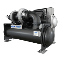
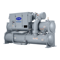
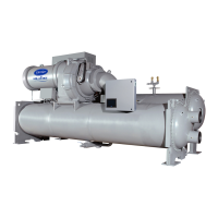
19XR Two-Stage High-Efficiency Semi-Hermetic
Centrifugal Liquid Chillers
with PIC 5 Controls
Version 3.3


 Loading...