Manufacturer reserves the right to discontinue, or change at any time, specifications or designs without notice and without incurring obligations.
Catalog No. 04-53300170-01 Printed in U.S.A. Form 30MP-4T Pg 1 8-17 Replaces: 30MP-3T
Controls, Start-Up, Operation,
Service, and Troubleshooting
CONTENTS
Page
SAFETY CONSIDERATIONS. . . . . . . . . . . . . . . . . . . . .2,3
GENERAL . . . . . . . . . . . . . . . . . . . . . . . . . . . . . . . . . . . . . . 3-7
Conventions Used in this Manual . . . . . . . . . . . . . . . . 3
Basic Controls Usage . . . . . . . . . . . . . . . . . . . . . . . . . . . . 3
CONTROLS . . . . . . . . . . . . . . . . . . . . . . . . . . . . . . . . . . . 7-36
General . . . . . . . . . . . . . . . . . . . . . . . . . . . . . . . . . . . . . . . . . . 7
Main Base Board (MBB). . . . . . . . . . . . . . . . . . . . . . . . . . 7
AUX Board (AUX) . . . . . . . . . . . . . . . . . . . . . . . . . . . . . . . . 7
Energy Management Module (EMM) . . . . . . . . . . . . . . 7
Current Sensor Board (CSB) . . . . . . . . . . . . . . . . . . . . . 7
Expansion Valve (EXV) Board . . . . . . . . . . . . . . . . . . . . 7
Enable/Off/Remote Control Switch . . . . . . . . . . . . . . . 7
Emergency On/Off Switch. . . . . . . . . . . . . . . . . . . . . . . . 7
Board Addresses . . . . . . . . . . . . . . . . . . . . . . . . . . . . . . . . 7
Control Module Communication . . . . . . . . . . . . . . . . . 7
Carrier Comfort Network
®
Interface . . . . . . . . . . . . . 13
Sensors . . . . . . . . . . . . . . . . . . . . . . . . . . . . . . . . . . . . . . . . . 15
• COOLER LEAVING FLUID SENSOR
• COOLER ENTERING FLUID SENSOR
• CONDENSER LEAVING FLUID SENSOR
• CONDENSER ENTERING FLUID SENSOR
• COMPRESSOR RETURN GAS
TEMPERATURE SENSOR
• OUTDOOR-AIR TEMPERATURE SENSOR
• DUAL LEAVING WATER TEMPERATURE SENSOR
• DISCHARGE TEMPERATURE THERMISTOR
• SPACE TEMPERATURE SENSOR
Energy Management Module . . . . . . . . . . . . . . . . . . . . 16
Loss-of-Cooler Flow Protection . . . . . . . . . . . . . . . . . 16
Condenser Flow Protection . . . . . . . . . . . . . . . . . . . . . 16
Thermostatic Expansion Valves (TXV) . . . . . . . . . . 16
Electronic Expansion Valves (EXV) . . . . . . . . . . . . . 17
Capacity Control . . . . . . . . . . . . . . . . . . . . . . . . . . . . . . . . 17
• MINUTES LEFT FOR START
• MINUTES OFF TIME
• CAPACITY CONTROL OVERRIDES
Time, Day, and Date. . . . . . . . . . . . . . . . . . . . . . . . . . . . . 20
Operation of Machine Based on Control Method. . 21
Cooling Set Point Select . . . . . . . . . . . . . . . . . . . . . . . . 25
Ice Mode . . . . . . . . . . . . . . . . . . . . . . . . . . . . . . . . . . . . . . . . 25
Cooler Pump Control. . . . . . . . . . . . . . . . . . . . . . . . . . . . 25
Alarm Routing. . . . . . . . . . . . . . . . . . . . . . . . . . . . . . . . . . . 25
Cooler Pump Sequence of Operation . . . . . . . . . . . 27
Condenser Pump/Condenser Fan Output
Control . . . . . . . . . . . . . . . . . . . . . . . . . . . . . . . . . . . . . . . . 27
Configuring and Operating Dual Chiller Control. . 27
Temperature Reset. . . . . . . . . . . . . . . . . . . . . . . . . . . . . . 31
Demand Limit . . . . . . . . . . . . . . . . . . . . . . . . . . . . . . . . . . . 34
• DEMAND LIMIT (2-Stage Switch Controlled)
• EXTERNALLY POWERED DEMAND LIMIT
(4 to 20 mA Controlled)
• DEMAND LIMIT (CCN Loadshed Controlled)
Cooling Set Point (4 to 20 mA) . . . . . . . . . . . . . . . . . . 34
Page
Digital Scroll Option . . . . . . . . . . . . . . . . . . . . . . . . . . . . 36
PRE-START-UP . . . . . . . . . . . . . . . . . . . . . . . . . . . . . . .36,37
System Check. . . . . . . . . . . . . . . . . . . . . . . . . . . . . . . . . . . 36
START-UP AND OPERATION. . . . . . . . . . . . . . . . . 37-40
Actual Start-Up. . . . . . . . . . . . . . . . . . . . . . . . . . . . . . . . . . 38
Check Refrigerant Charge. . . . . . . . . . . . . . . . . . . . . . . 38
Check Compressor Oil Level. . . . . . . . . . . . . . . . . . . . 39
Adjust Oil Charge . . . . . . . . . . . . . . . . . . . . . . . . . . . . . . . 39
Operating Limitations . . . . . . . . . . . . . . . . . . . . . . . . . . . 40
• TEMPERATURES
• VOLTAGE — ALL UNITS
OPERATION SEQUENCE. . . . . . . . . . . . . . . . . . . . . . . . 40
SERVICE . . . . . . . . . . . . . . . . . . . . . . . . . . . . . . . . . . . . . 40-52
Service Test. . . . . . . . . . . . . . . . . . . . . . . . . . . . . . . . . . . . . 40
Charging . . . . . . . . . . . . . . . . . . . . . . . . . . . . . . . . . . . . . . . . 41
Electronic Components . . . . . . . . . . . . . . . . . . . . . . . . . 41
• CONTROL COMPONENTS
Electronic Expansion Valve (EXV). . . . . . . . . . . . . . . 41
EXV Troubleshooting Procedure . . . . . . . . . . . . . . . . 42
Compressor Replacement . . . . . . . . . . . . . . . . . . . . . . 44
30MP Cooler and 30MPW Condenser . . . . . . . . . . . 44
• BRAZED-PLATE COOLER AND CONDENSER
HEAT EXCHANGER REPLACEMENT
• BRAZED-PLATE COOLER AND CONDENSER
HEAT EXCHANGER CLEANING
Water Treatment . .
. . . . . . . . . . . . . . . . . . . . . . . . . . . . . . 45
Oil Charge . . . . . . . . . . . . . . . . . . . . . . . . . . . . . . . . . . . . . . 45
Check Refrigerant Feed Components . . . . . . . . . . . 45
• FILTER DRIER
• MOISTURE-LIQUID INDICATOR
• THERMOSTATIC EXPANSION VALVE (TXV)
• MINIMUM LOAD VALVE
• PRESSURE RELIEF DEVICES
Check Unit Safeties . . . . . . . . . . . . . . . . . . . . . . . . . . . . . 46
Thermistors . . . . . . . . . . . . . . . . . . . . . . . . . . . . . . . . . . . . . 46
Pressure Transducers . . . . . . . . . . . . . . . . . . . . . . . . . . 46
Chilled Water Flow Switch . . . . . . . . . . . . . . . . . . . . . . 47
Strainer . . . . . . . . . . . . . . . . . . . . . . . . . . . . . . . . . . . . . . . . . 52
Replacing Defective Modules . . . . . . . . . . . . . . . . . . . 52
MAINTENANCE . . . . . . . . . . . . . . . . . . . . . . . . . . . . . . . . . 52
Recommended Maintenance Schedule. . . . . . . . . . 52
TROUBLESHOOTING . . . . . . . . . . . . . . . . . . . . . . . . 52-71
Complete Unit Stoppage and Restart. . . . . . . . . . . . 52
• GENERAL POWER FAILURE
• UNIT ENABLE-OFF-REMOTE CONTROL SWITCH
IS OFF
• CHILLED FLUID PROOF-OF-FLOW SWITCH OPEN
• OPEN 24-V CONTROL CIRCUIT BREAKER(S)
• COOLING LOAD SATISFIED
• THERMISTOR FAILURE
• ENABLING AND DISABLING COMPRESSORS
• COMPRESSOR DISCHARGE CHECK VALVE
• LOW SATURATED SUCTION
• COMPRESSOR SAFETIES
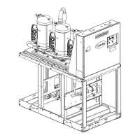
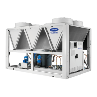
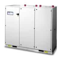
AquaSnap
®
30MPA,MPW015-071
Liquid Chillers with Scroll Compressors
and ComfortLink Controls


 Loading...