8
Before the start-up of the refrigeration system, the complete
installation, including the refrigeration system must be
verified against the installation drawings, dimensional
drawings, system piping and instrumentation diagrams and
the wiring diagrams.
During the installation test national regulations must be
followed. If the national regulation does not specify any
details, refer to standard EN 378-2 as follows:
External visual installation checks:
• Compare the complete installation with the refrigeration
system and power circuit diagrams.
• Check that all components comply with the design
specifications.
• Check that all protection documents and equipment
provided by the manufacturer (dimensional drawings,
P&ID, declarations etc.) to comply with the regulations
are present.
• Verify that the environmental safety and protection and
devices and arrangements provided by the manufacturer
to comply with the regulations are in place.
• Verify that all documents for pressure containers, certifi-
cates, name plates, files, instruction manuals provided
by the manufacturer to comply with the regulations
are present.
• Verify the free passage of access and safety routes.
• Verify the instructions and directives to prevent the
deliberate removal of refrigerant gases.
• Verify the installation of connections.
• Verify the supports and fixing elements (materials,
routing and connection).
• Verify the quality of welds and other joints.
• Check the protection against mechanical damage.
• Check the protection against heat.
• Check the protection of moving parts.
• Verify the accessibility for maintenance or repair and
to check the piping.
• Verify the status of the valves.
• Verify the quality of the thermal insulation.
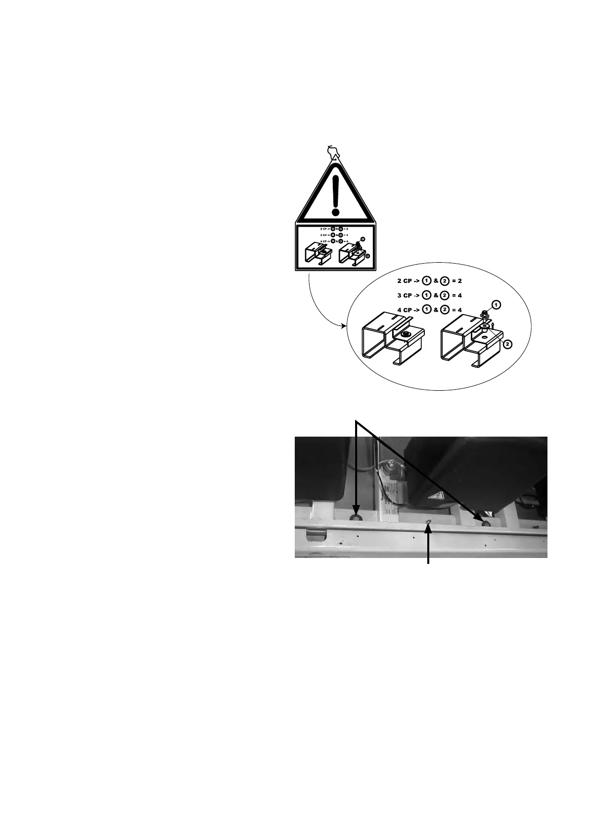
Compressor ange to be removed
Chassis xing to be kept
IMPORTANT: The compressor assemblies are “floating”
on rubber blocks between the unit chassis and the sub-
assembly chassis (they are not visible). To protect the
piping during transport, a flange is installed in the factory.
This flange must be removed on site.
The flange is identified by red rings. A label attached to
the compressor sub-assembly warns the installer.
 Loading...