7
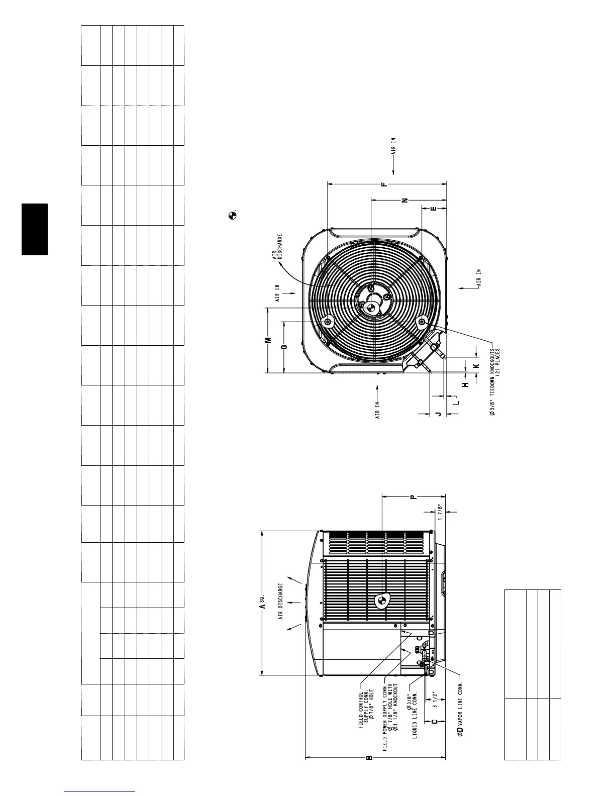
DIMENSIONS
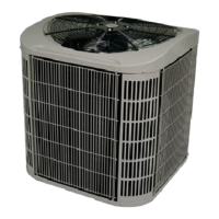
UNIT SERIES
ELECTRICAL
CHARACTERISTICS
A B C D E F G H J K L M N P
24ABA318 0 X 0 0 0 25 3/4” 25 1/8” 33/4” 5/8” 4 7/ 16” 21 1/4” 91/8” 5/16” 3” 2 13/16” 1/2” 12 1/2” 12 3/ 8” 12 3/8”
24ABA324 0 X 0 0 0 25 3/4” 25 1/8” 33/4” 5/8” 4 7/16” 21 1/4” 91/8” 5/16” 3” 2 13/16” 1/2” 13” 11 7/8” 12 3/8”
24ABA330 0 X 0 0 0 25 3/4” 28 1/2” 33/4” 3/4” 4 7/16” 21 1/4” 91/8” 5/16” 3” 2 13/16” 1/2” 12 1/4” 13 3/ 4” 12 3/4”
24ABA336 0 X 0 0 0 25 3/4” 35 5/16” 33/4” 3/4” 4 7/16” 21 1/ 4” 91/8” 5/16” 3” 2 13/16” 1/2” 12” 13” 14 3/4”
24ABA342 0 X 0 0 0 31 3/16” 32 7/16” 37/8” 7/8” 6 9/16” 24 11/16” 91/8” 5/16” 3” 2 15/ 16” 5/8” 16 1/4” 16 1/4” 13 3/4”
24ABA348 0 X 0 0 0 31 3/16” 39 1/4” 37/8” 7/8” 6 9/16” 24 11/16” 91/8” 5/16” 3” 2 15/16” 5/8” 17 1/4” 17 1/4” 19 3/4”
24ABA360 0 X 0 0 0 35” 39 1/4” 37/8” 7/8” 6 9/16” 28 7/16” 91/8” 5/16” 3” 2 15/16” 5/8” 19 3/4” 19 3/4” 18 3/8”
2 0 8 --- 2 3 0 --- 1 --- 6 0
2 3 0 --- 1 --- 6 0
208/230--- 3---60
4 6 0 --- 3 --- 6 0
X=YES
0=NO
1. Allow 30” clearance to service side of unit, 48” a bove unit, 6” on one side, 12”
on remaining side, and 24” between units for proper airflow.
2. Minimum outdoor operating ambient in cooling mode is 55 _F, max. 125_ F.
3. Series designation is the 13th position of the unit model number.
4. Center of gravity
5. For hurricane tie downs, contact distributor for details and PE Certification
(Professional Engineer), if required.
UNIT SIZE
MINIMUM MOUNTING
PAD DIMENSIONS
18, 24, 30, 36 26” X 26”
42, 48 31 1/2” X 31 1/2”
60 35” X 35”
24ABA3