CONNECTING ELECTRICAL WIRING
19-3 ELECTRICAL DATA
NOTES
1. Starting Current duration is usually less than 1 Second.
2. Operating Conditions.
* @ 35ºC db outdoor temperature :
27/19ºC db/wb Indoor Temperature. High air flow of indoor unit
** @ 43ºC db outdoor temperature :
27/19ºC db/wb Indoor Temperature. High air flow of indoor unit
*** @ 46ºC db outdoor temperature :
29/19ºC db/wb Indoor Temperature. High air flow of indoor unit
**** @ 52ºC db outdoor temperature :
27/19ºC db/wb Indoor Temperature. High air flow of indoor unit
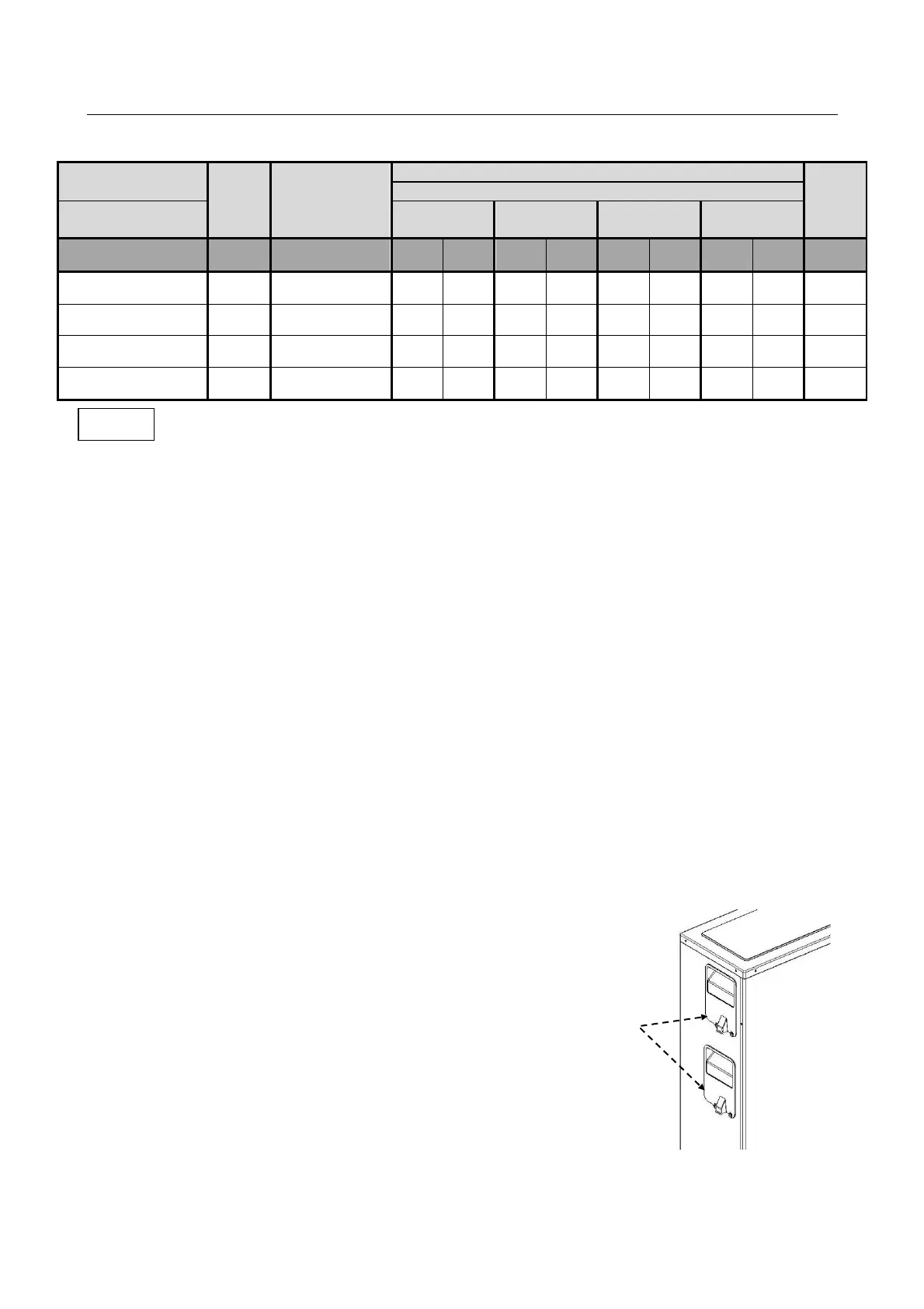
19-4 ELECTRICAL CONNECTING TO OUTDOOR UNIT
Description of Electrical Connections of Side Discharge Outdoor Unit
1. Remove the screw fixing service door.
And remove from unit.
2. Connect power cable to electrical box of outdoor unit
as per caution - field electrical wiring.
3. Connect control cable to electrical box of outdoor unit
as per caution - field electrical wiring.
4. Route wires from disconnect through openings provided
and into the unit electrical box.
 Loading...