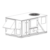
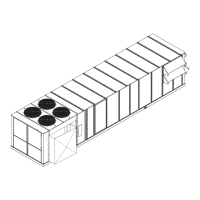
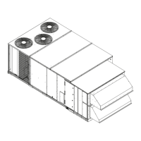
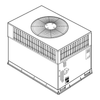
Do you have a question about the Carrier 48/50PG C03-14 and is the answer not in the manual?
General safety precautions, symbols, and signal words.
Warning about electrical shock hazard during service.
Caution against using jumpers or tools to bypass control components.
Overview of units, ComfortLink controls, and Puron refrigerant.
Introduction to the ComfortLink control system and its interface.
Explanation of conventions used for discussing configuration points.
Checks before starting the unit installation and operation.
Instructions regarding compressor mounting bolts.
Location and importance of refrigerant service ports.
General operation and importance of crankcase heaters.
Determining and correcting compressor rotation direction.
Wiring for different power supply voltages.
Checking electrical connections within control boxes.
Fan belt and pulley adjustment and fan direction.
Factory settings and adjustments for condenser fans.
Filter installation and option details.
Requirement for inlet screens to be in place.
Use of Motormaster control and wind baffles for Humidi-MiZer units.
Ensuring accessories are installed and wired correctly.
Instructions for changing orifices for altitude or LP gas.
Inspecting gas heat section and verifying gas pressures.
Information on starting up units with the EnergyX option.
Importance of documenting set points and configuration changes.
Wiring accessory thermostats and default unit control type.
Wiring and configuration for direct wired space sensors.
Connecting and configuring the T-58 communicating sensor.
CCN communication configuration for linkage.
Using System Pilot as a communication space sensor.
Configuration for thermidistat and humidity switch inputs.
Humidistat input for Humidi-MiZer units.
Humidity sensor input for Humidi-MiZer and economizer options.
Configuring CCN element number, bus number, and baud rate.
Quick configuration settings for field-installed accessories.
Configuration for field-installed economizers.
Configuration for field-installed power exhaust.
Configuration for field-installed electric heat.
Configuration for fire shutdown switch input.
Output to indicate current alarm status.
Setting up occupied and unoccupied time schedules.
Changing output status for economizer, power exhaust, etc.
Changing output status for indoor and outdoor fans.
Changing output status for individual compressors.
Changing output status for Humidi-MiZer modes and valves.
Thermostat inputs for cooling and heating control.
Humidity switch input for Humidi-MiZer units.
Input for remote occupancy switch.
Input for fire shutdown or smoke detector.
Output to indicate current alarm status.
Configuring local display settings like units and language.
Configuring factory options and field accessories.
Setting the control start-up delay after power interruption.
Defining temperature control based on thermostat or sensor input.
Determining alternative cooling and Humidi-MiZer staging.
Operating indoor fan based on occupancy status.
Enabling diagnostic alert for fan status issues.
Identifying fan status switch configuration.
Identifying filter status switch configuration.
Identifying fire shutdown switch configuration.
Identifying remote occupancy switch configuration.
Setting settling time for supply air temperature.
Identifying if RAT sensor is installed on SPTO input.
Identifying if RH sensor is installed on OAQ input.
Identifying space humidity switch configuration.
Factor for start time bias equation for cooling.
Factor for start time bias equation for heating.
Hierarchy of control system modes: System, HVAC, Occupied, and Control Type.
Overall state of the unit: Disabled, Enabled, or Service Test.
Allowed HVAC modes: Disabled, Fan Only, Cool, and Heat.
Disabling HVAC mode, available on network connections.
Actual setpoint used for control during cooling mode.
Actual setpoint used for control during heating mode.
Current state of assumed space occupancy.
Occupancy state due to an override.
Indicates if linkage communication is established.
Indicates if demand limit is placed on unit capacity.
Prevents compressor operation due to outdoor temperature.
Prevents heating operation due to outdoor temperature.
Prevents economizer cooling due to outdoor temperature.
Unit operation covering cooling, dehumidification, heating, and ventilation.
Force/write to occupancy via external device, NVI_OCC, or Linkage.
Remote occupancy switch configuration (Normally Open/Closed).
Occupancy options determined by schedule number and global broadcast.
IDF relay operation based on thermostat or occupancy calls.
IDF relay operation based on thermostat or occupancy calls.
IDF relay operation based on space sensor mode.
SAT Heat Mode Sensing configuration.
How the unit enters and leaves the cooling mode.
Conditions for entering cooling mode with thermostat control.
Conditions for entering cooling mode with space sensor control.
How the unit decides to satisfy cooling demand and stages.
Two ways of requesting stages when thermostat control is enabled.
Adaptive anticipation control weighing space demand against supply air trend.
Determining available compressors and providing stages.
Variable outdoor airflow control for condenser pressure.
OFM control via OFC for standard units.
OFM control with Motormaster for Humidi-MiZer units.
Unit enters heating mode based on demand and outdoor temperature.
Conditions for entering heating mode with thermostat control.
Conditions for entering heating mode with space sensor control.
SAT Heat Mode Sensing configuration.
Deciding how to satisfy heating demand based on unit configuration.
Requesting stages when thermostat control is enabled.
Energizing/de-energizing MBB heat stage relays.
Economizer control under thermostat mode.
Economizer control under space sensor mode.
Algorithm for maintaining space temperature using economizer when unoccupied.
How dehumidification demand is seen via humidistat or RH sensor.
Cooling mode functions: Reheat1, Reheat2, and Reheat1/Reheat2.
Outdoor fan control logic for reheat modes.
Forcing system operation in stages of Reheat1 or Reheat2 mode.
Configuring IAQ sensors that provide 4 to 20 mA.
Measuring indoor air quality using a switch input.
OAQ analog input usage for ventilation and lockout.
Determining if IAQ algorithm can turn on the indoor fan.
Determining if IAQ switch input can turn on the indoor fan.
Defining fan speed used in Ventilation mode.
Defining fan speed used when IAQ Override is active.
Defining fan speed used in Free Cooling at low cool mode.
Defining fan speed used in Free Cooling at high cool mode.
Defining intermediate fan speed used when mechanical cooling is requested.
Defining fan speed used when Hot Gas Reheat is requested.
Defining intermediate fan speed used when in heating mode.
CCN address the rooftop is assigned.
CCN bus the rooftop is assigned.
CCN baud rate configuration.
Periodically sending time and date onto the CCN bus.
Periodically broadcasting outside-air temperature.
Broadcasting internal time schedule when configured.
Responding to and acknowledging broadcasting on the bus.
Determining what schedule the control may follow.
Option to accept global holidays from broadcast message.
Deciding how long an override occurs when initiated.
Displaying remaining hours of an override.
Allowing users to disable override function.
Overriding cooling algorithm to limit capacity to control power usage.
Establishing linkage with a Linkage Coordinator without configuration settings.
Optimizing unit and zone performance through data synchronization.
Modifications during linkage control for anticipatory space control.
Understanding system alerts and alarms and their responses.
CCN network notification of striking alerts.
Normally open 24 vac output for alarm relay indication.
Conditions causing the unit to not provide heating or cooling.
Steps to diagnose and reset alarms before restarting.
Viewing and clearing unit alarms and alerts.
Alerts when current sensor does not detect compressor current.
Alerts when current sensor detects current when compressor should be off.
Alerts for saturated condensing temperature thermistor failure.
Alerts for saturated suction temperature thermistor failure.
Alerts for outdoor air temperature thermistor failure.
Alerts for space temperature thermistor failure.
Alerts for return air thermistor failure.
Alerts for space relative humidity sensor failure.
Alert for circuit C saturated condensing temperature thermistor failure.
Alert for circuit C saturated suction temperature thermistor failure.
Alerts for circuit suction pressure transducer failure.
Alerts for compressor current sensor failure.
Alerts for circuit loss of charge.
Alerts for circuit high discharge pressure.
Alerts for circuit low refrigerant pressure.
Alerts for circuit failure to pressurize.
Alert for serial EEPROM chip failure on MBB.
Alert for serial EEPROM storage failure error.
Alert for critical serial EEPROM storage fail error.
Alert for analog-to-digital conversion chip failure.
Alarms for circuits with 3 strikes or locked out by another alarm.
Alert for MBB losing communication with EMM.
Alert for MBB losing communication with ECB.
Alert for ECB losing communication with Belimo Actuator.
Alert for MBB losing communication with OAU.
Alarm for MBB failing to communicate with a Linkage device.
Alarm for shutdown input being open or closed.
Alert for filter status switch sensing a plugged filter.
Alerts related to fan status switch and fan contactor status.
Alert for Y2 input activated without Y1 input in thermostat mode.
Alert for W2 input activated without W1 input in thermostat mode.
Alert for simultaneous Y and W inputs in thermostat mode.
Alerts generated by Belimo actuator for economizer damper issues.
Alert for OAQ input being less than 3.5 mA.
Alerts generated by OAU device for motor failure, dirty filter, low CFM, or general alarm.
Visual checks for MBB and ECB control boards using red status LEDs.
Troubleshooting communication issues between boards.
LEN and CCN communication resistance values for board diagnostics.
General analysis of cooling problems and their remedies.
Causes and remedies for compressor and fan not starting.
Causes and remedies for compressor cycling issues.
Causes and remedies for continuous compressor operation.
Causes and remedies for high condenser pressures.
Causes and remedies for condenser fans not operating.
Causes and remedies for excessive suction pressure.
Causes and remedies for suction pressure being too low.
General analysis of Humidi-MiZer service issues.
Troubleshooting subcooling reheat mode activation.
Troubleshooting hot gas reheat mode activation.
Troubleshooting lack of dehumidification demand.
Troubleshooting CRC relay operation.
Troubleshooting CV or RH1 valve operation.
Troubleshooting RH2 valve operation.
Troubleshooting low latent capacity.
Troubleshooting low sensible capacity.
Troubleshooting low suction and high discharge pressure.
Troubleshooting RH2 valve cycling.
Troubleshooting circuit operation when circuit A is off.
General analysis of economizer problems.
Troubleshooting when the economizer damper does not move.
Troubleshooting economizer operation limited to minimum position.
Troubleshooting economizer position less than minimum.
Troubleshooting economizer not returning to minimum position.
Troubleshooting damper closing on power loss.
Troubleshooting economizer not at configured minimum position.
General gas heating service analysis and IGC board logic.
Electric heating service analysis.
Analysis of gas heating problems and remedies.
Causes and remedies for heat not turning on.
Causes and remedies for burners not igniting.
Causes and remedies for inadequate heating.
Causes and remedies for poor flame characteristics.
Causes and remedies for burners not turning off.
Overview of components and accessories for 48/50PG and 48/50PM units.
Central component of ComfortLink system, controls unit operation.
Controls economizer actuator and has inputs for IAQ/OAQ, enthalpy, and RH sensors.
Controls gas heat units, direct spark ignition, and monitors safety switches.
Connection point for accessories, CCN, and LEN communications.
Keypad interface for accessing information and testing the unit.
Hand-held display for control access and data, similar to Scrolling Marquee.
Connecting units to the CCN system using shielded cable.
Factory installed energy recovery ventilator for pre-conditioning outside air.
Kits for various field-installed accessories.
Warnings about personal injury or death from electrical shock.
Warnings about personal injury, death, or equipment damage.
Warnings about personal injury, death, or property damage from fire or explosion.
Inspect unit interior for cleaning at beginning of season and as operating conditions require.
Routine cleaning of coil surfaces for proper operation and longevity.
Removing fibers and dirt from coils using vacuum or brush.
Monthly cleaning with low velocity water stream for coils in coastal or industrial environments.
Cleaning condenser coil surfaces using only water.
Monthly cleaning recommendations for round-tube coils.
Cautions against using harsh chemicals on coils.
Step-by-step guide for applying Totaline coil cleaner.
Cleaning the condensate drain pan annually.
Cleaning or replacing filters at start of heating/cooling season.
Cleaning screens with steam or hot water and detergent.
Inspecting main burners for deterioration or blockage.
Inspecting flue collector box and heat exchanger cells.
Periodic cleaning of combustion-air blower for proper airflow.
Lubrication requirements for unit components.
Compressor oil requirements and handling precautions.
Cautions regarding POE oils and potential damage to roofing materials.
Information on permanently sealed bearings for indoor fan.
Lubrication intervals and types for indoor fan bearings.
Steps to adjust fan speeds by altering pulley settings.
Procedure for adjusting belt tension on the evaporator fan.
Cautions regarding repair procedures affecting pressure rating or corrosion resistance.
Using service repair kits for repairing tube leaks in crosstubes.
Checking sensor inputs via Scrolling Marquee display.
Damper behavior during power failure.
Removing noncondensables and ensuring a tight, dry system before charging.
Method requiring a vacuum pump capable of pulling a minimum vacuum.
Vacuum pump method for systems without liquid water.
Warnings about Puron refrigerant systems.
Using standard evacuating techniques and weighing in refrigerant.
Using cooling charging charts to add or remove refrigerant.
Steps for using cooling charging charts for standard units.
Using cooling charging charts for Humidi-MiZer units.
Steps for adjusting the gas valve opening and closing response.
Steps for removing the main burner assembly.
Cleaning burners and adjusting spark gap.
Compressor rotation, overcurrent, overtemperature, and high-pressure switch protection.
Detecting losses in compressor power.
Internal overcurrent and overtemperature protection for indoor-fan motors.
Internal overtemperature protection for condenser-fan motors.
Shutting down circuit if SSP is below alarm set point for extended period.
Devices to protect against damage from excessive pressures.
Overcurrent protection for control circuit by circuit breaker.
Obtaining replacement parts from Carrier distributor.
MBB, ECB, and IGC control boards have LED lights for diagnostics.
Information on EnergyXv2 Supplement Installation Instructions.
Display of unit status items like HVAC mode, occupancy, and temperatures.
Continuation of unit status items like component run hours.
Configuration parameters for various modes like COOL, HEAT, ECON, IAQ.
Continuation of configuration parameters for OAU, TRIM, and CCN.
Continuation of configuration parameters for CCN.
Table detailing service test modes and submodes.
Table listing temperature related display items.
Table listing pressure related display items.
Table listing set points for occupied/unoccupied cooling and heating.
Table listing unit inputs for thermostat, sensors, and switches.
Table listing unit outputs for fan, compressor, heat, economizer, and alarm.
Configuration parameters for Display, Unit, Thermostat Control Type, Fan Status, etc.
Configuration parameters for Cooling and Circuit settings.
Configuration parameters for Cooling, Humidimizer, Heat, and Economizer.
Configuration parameters for Heat, SAT, SPT, and Economizer.
Configuration parameters for Economizer, IAQ, OAQ, and RH sensors.
Configuration parameters for OAU, DCV, and Power Exhaust.
Configuration parameters for Adaptive Fan, Alarm Relay, PID, Linkage, and Sensor Calibration.
Configuration parameters for CCN Broadcast, Schedule, Loadshed, and Max Stages.
Additional tables for local display and CCN configurations.
Configuration for time clock settings including schedules and holidays.
Tables specific to CCN communication for alarms and controller ID.
Table detailing operating modes like HVAC, Cool, Heat, and Economizer.
Continuation of operating modes, including OAU and Demand Limiting.
Continuation of operating modes, including Alarms.
Control logic for single-circuit units based on thermostat and economizer.
Control logic for dual-circuit units based on thermostat configuration.
Control logic for dual-circuit units based on digital thermostat configuration.
Fan performance data for 48PGD03 vertical units.
Fan performance data for 48PGD04 vertical units.
Fan performance data for 48PGE05 vertical units.
Fan performance data for 48PGE06 vertical units.
Fan performance data for 48PGE07 vertical units.
Fan performance data for 48PGD07 vertical units.
Fan performance data for 48PGD08 vertical units.
Fan performance data for 48PGF08 vertical units.
Fan performance data for 48PGF09 vertical units.
Fan performance data for 48PGE06 vertical units.
Fan performance data for 48PGE07 vertical units.
Fan performance data for 48PGE08 vertical units.
Fan performance data for 48PGE09 vertical units.
Fan performance data for 48PGD14 vertical units.
Fan performance data for 48PGF14 vertical units.
Fan performance data for 48PGE08 horizontal units.
Fan performance data for 48PGE14 horizontal units.
Fan performance data for 48PGF05 horizontal units.
Fan performance data for 48PGF06 horizontal units.
Fan performance data for 48PGF07 horizontal units.
Fan performance data for 48PGD07 horizontal units.
Fan performance data for 48PGE08 horizontal units.
Fan performance data for 48PGE09 horizontal units.
Fan performance data for 48PGD12 horizontal units.
Fan performance data for 48PGD14 horizontal units.
Fan performance data for 48PGF14 horizontal units.
Fan performance data for 50PG03 horizontal units.
Fan performance data for 50PG04 horizontal units.
Fan performance data for 50PG14 horizontal units.
Fan performance data for 50PG05 horizontal units.
Fan performance data for 50PG07 horizontal units.
Fan performance data for 50PG08 horizontal units.
Fan performance data for 50PG09 horizontal units.
Fan performance data for 50PGD12 horizontal units.
Fan performance data for 50PGE08 horizontal units.
Fan performance data for 50PGE09 horizontal units.
Fan performance data for 50PMD16 horizontal units.
Fan performance data for 48PMD16 horizontal units.
Fan performance data for 48PMD20 horizontal units.
Fan performance data for 48PME20 horizontal units.
Fan performance data for 48PMD24 horizontal units.
Fan performance data for 48PME24 horizontal units.
Fan performance data for 48PMD28 horizontal units.
Fan performance data for 48PME28 horizontal units.
Fan performance data for 50PM24 horizontal units.
Fan performance data for 50PM20 horizontal units.
Fan performance data for 50PM24 horizontal units.
Fan performance data for 50PM28 horizontal units.
Data for air quantity limits for various unit models.
Data for air quantity limits for various unit models.
Data for air quantity limits for various unit models.
Data for air quantity limits for various unit models.
Continuation of motor specifications for 48/50PG evaporator fans.
Continuation of motor specifications for 48PM16-28 evaporator fans.
Motor specifications for 50PM16-28 evaporator fans.
Continuation of motor specifications for 50PM16-28 evaporator fans.
Fan RPM values based on motor pulley settings for 48PM16-28 units.
Pressure drop data for accessories and factory-installed options for 48/50PM16-28 units.
Electric heat static pressure drop data for 50PM16-28 units.
Parameters related to unit configuration settings.
Configuration parameters for Cooling and Circuit settings.
Configuration parameters for Cooling, Humidimizer, Heat, and Economizer.
Configuration parameters for Heat, SAT, SPT, and Economizer.
Configuration parameters for Economizer, IAQ, OAQ, and RH sensors.
Configuration parameters for OAU, DCV, and Power Exhaust.
Configuration parameters for Adaptive Fan, Alarm Relay, PID, Linkage, and Sensor Calibration.
Configuration parameters for CCN Broadcast, Schedule, Loadshed, and Max Stages.
Pre-start-up checks for unit installation and packaging removal.
Start-up procedures including electrical, temperatures, and pressures.
| Model Number | 48/50PG C03-14 |
|---|---|
| Category | Air Conditioner |
| Refrigerant Type | R-410A |
| Voltage | 208/230V |
| Phase | 1 |
| Energy Efficiency Ratio (EER) | Up to 11.0 |
| Dimensions (Outdoor Unit) | 31.5 inches |


 Loading...