2
GENERAL
The EconoMi$er
®
X system utilizes the latest technology
available for integrating the use of free cooling with mechanical
cooling for packaged rooftop units. The code compliant W7220
control system optimizes energy consumption, zone comfort,
and equipment cycling by operating the compressors when the
outdoor-air temperature is too warm, integrating the compressor
with outdoor air when free cooling is available, and locking out
the compressor when outdoor-air temperature is too cold.
Demand controlled ventilation is supported.
NOTE: This EconoMi$er X system can be used with 1 or 2 speed
indoor fan motor units. All other speed settings listed are for future
use.
The EconoMi$er X system utilizes gear-drive technology with a
direct-mount spring return actuator that will close upon loss of
power. The EconoMi$er X system comes standard with fault
detection and diagnostics (FDD), an outdoor air temperature
sensor, and mixed air temperature sensor (also called supply air
temperature sensor). Outdoor enthalpy, indoor (return) dry bulb
or enthalpy, and CO
2
sensors are available for field installation.
Separate barometric relief dampers provide natural building pres-
surization control. An optional power exhaust system is available
for applications requiring even greater exhaust capabilities. The
power exhaust set point is adjustable at the EconoMi$er X
controller.
See Table 1 for package usage. See Table 2 for package contents.
See Table 3 for sensor usage.
* Shipped in hardware kit for field installation.
* Includes HH57AC081 sensor and wiring harness.
† Accessory CO
2
sensors.
** Accessory aspirator boxes required for duct-mounted applications.
††CRBDCIOX005A00 is an accessory that contains both 33ZCSENS-
CO2 and 33ZCASPCO2 accessories.
NOTE: Dry Bub sensor HH79AH001 is included in the kit. Dry Bulb sen-
sor HH79ZZ007 can be used as a replacement part.
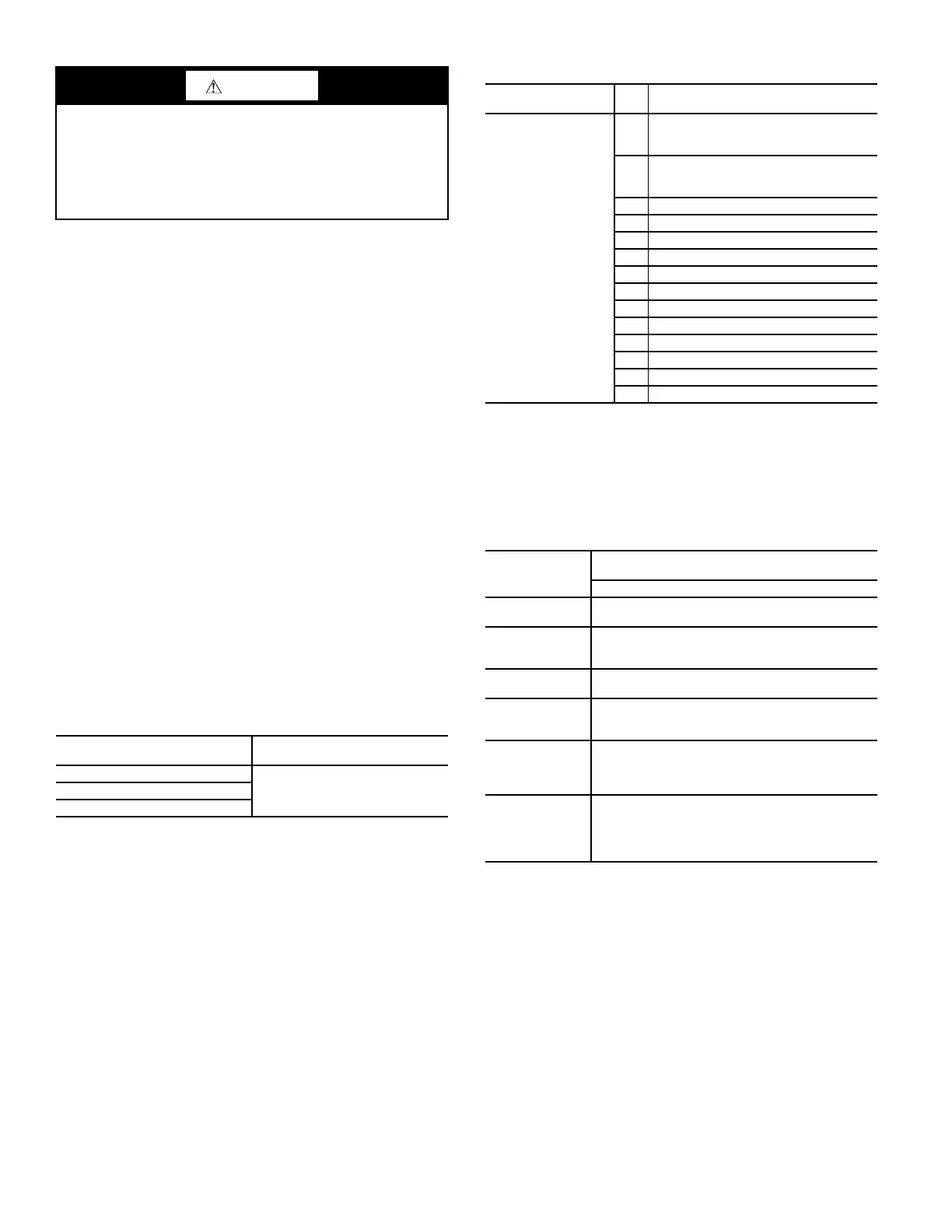
CAUTION
PERSONAL INJURY HAZARD
Failure to follow this caution can result in personal injury and
damage to the unit.
Cover the duct opening as a precaution so objects cannot fall
into the return duct opening. Be sure to remove the cover when
installation is complete.
Table 1 — Usage Chart
MODEL NUMBER/SIZE
ECONOMI$ER
®
X
PART NUMBER
48/50FC 08-14
CRECOMZR085A00582K/559K 08-14
RGV/RAV 090-150
Table 2 — Package Contents
ECONOMIZER
PART NUMBER
QTY CONTENTS
CRECOMZR085A00
1
EconoMi$er Damper Assembly with
Actuator and HH79AH001 (HW: C7250)
Outside Air Sensor
1
HW63AW002 (HW: W7220) Controller
with Attached Harness
48TCHSRAEHA00*
1 HH79HH001 Mixed Air Temp Sensor*
Hood Assembly with Top and 2 Sides
1 Hood O/A Panel
1 Aluminum Filter
1 Hardware Bag*
1 Sensor Harness 50HE403859*
1 Barometric Relief Hood Assembly
1 O/A Small Blank Off
1 O/A Large Blank Off
1 R/A Small Blank Off
1 R/A Large Blank Off
1 O/A Panel Access Door
LEGEND
HW — Honeywell
O/A — Outside Air
R/A — Return Air
Table 3 — EconoMi$er X Sensor Usage
APPLICATION
ECONOMI$ER X WITH OUTDOOR AIR
DRY BULB SENSOR
ACCESSORIES REQUIRED
Outdoor Air
Dry Bulb
The HH79AH001 (HH79ZZ007) outdoor air dry
bulb sensor is factory installed on economizer.
Mixed Air
Sensor
HH79AH001 (HH79ZZ007) provided with
economizer and field installed in blower
compartment.
Single
Enthalpy
HH57AC081
Differential
Dry Bulb or
Enthalpy
CRDIFRASN01A00* (When available, or MicroMetl
part number 9901-2022-DIFF JC2)
CO
2
for DCV
Control using
a Wall-Mounted
CO
2
Sensor
33ZCSENCO2
or
CGCDXSEN004A00
CO
2
for DCV
Control using
a Duct-Mounted
CO
2
Sensor
33ZCSENCO2 or
CGCDXSEN004A00†
and
33ZCSENCO2 or
CGCDXASP00100**
or CRCBDIOX005A00††
 Loading...