3
ACCESSORIES AND COMPLIANCE
Accessories List
The EconoMi$er X system has several field-installed accessories
available to optimize performance. Refer to Table
4 for authorized
parts and power exhaust descriptions.
* When available order MicroMetl PN 9901-2022-DIFF JC2.
Compliance
Economizers meet California Energy Commission Title 24
mandatory section 120.2.i for Fault Detection and Diagnostic
controls.
Economizers meet ASHRAE 90.1 Fault Detection and Diagnostic
requirements.
Economizers meet IECC Fault Detection and Diagnostic
requirements.
NOTE: IECC requires differential return air sensor, which must be
ordered separately. See Accessory CRDIFRASN01A00.
INSTALLATION
See Fig. 1 for component locations.
1. Turn off power supply(s) and install lockout tag.
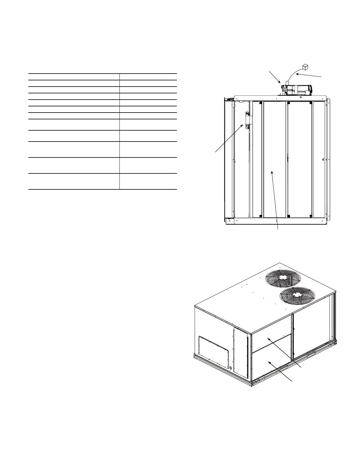
2. Remove the existing unit filter access panel. Raise the panel
and swing the bottom outward. The panel is now disengaged
from the track and can be removed and discarded. (See
Fig. 2.)
3. Remove the indoor coil access panel and discard. (See
Fig. 2.)
4. Slide the EconoMi$er X assembly into the rooftop unit. (See
Fig. 3.)
5. Slide the EconoMi$er X assembly all the way back and into
the horizontal R/A (Return Air) opening. (See Fig. 3.)
NOTE: Be sure that the arrow on the actuator motor is pointing to
“Run” and not to “Test.” If the arrow is at “Test,” the Economizer
damper will drive open.
6. Attach O/A (Outside Air) panel over the panel opening, then
lift the economizer. Match the ID (inside dimension) of the
panel with the ID of the economizer, then attach using pro-
vided screws. (See Fig. 4.)
7. If the EconoMi$er X system will be operating with an
enthalpy outside air sensor, remove the factory installed
HH79AH001 dry bulb sensor from the front face of the
economizer (see Fig. 1), and install the accessory enthalpy
sensor HH57AC081 in the same location. Connect the (2)
wire gray harness with plug from the EconoMi$er X
assembly to the enthalpy sensor. See page 7 for wiring
diagram. Refer to page 8 “Installing Optional HH57AC081
Outside Air Enthalpy Sensor” section for more details on
enthalpy settings.
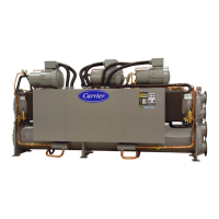
Fig. 1 — EconoMi$er X Component Locations
(CRECOMZR085A00 Shown)
Fig. 2 — Filter Access View
Table 4 — EconoMi$er
®
X Field-Installed Accessories
DESCRIPTION PART NUMBER
208/230-v 1PH Power Exhaust CRPWREXH028A01
460-v 3PH Power Exhaust CRPWREXH029A01
Enthalpy Sensor (OA) HH57AC081
Differential (Return) Sensor CRDIFRASN01A00*
CO
2
Sensor and Aspirator Box CRCBDIOX005A00
Return Air CO
2
Sensor (4 to 20 mA) CRCBDIOX002A00
CO
2
Room Sensor (4 to 20 mA)
33ZCSENCO2 or
CGCDXSEN004A00
Aspirator Box for Duct Mount CO
2
Sensor (4 to 20 mA)
33ZCASPCO2 or
CGCDXASP001A00
Economizer Angle Seal Kit for use with
unit's with Hinged Filter Door – for
Small Cabinet
CRPECONV003A00
Economizer Angle Seal Kit for use with
unit's with Hinged Filter Door – for
Large Cabinet
CRPECONV004A00
Economizer Angle Seal Kit for use with
unit's with Hinged Filter Door – for
Extra Large Cabinet
CRPECONV007B00
Actuator
HH79AH001
Outside Air
Temperature
Sensor
Outside Air
Damper
Wiring
Harness
Filter Access Panel
Indoor Coil Access Panel
 Loading...