4. Route thermostat wires through large hole in mounting
base. Remove outer sheath from wires for added flex-
ibility. Standard solid or multi-conductor thermostat wire
should be used from the thermostat to the unit. Size and
length considerations are as follows: for a maximum
distance from unit of 36 ft, use 22 AWG (American
Wire Gage) wire; for a maximum distance from unit
of 100 ft, use 18 AWG wire.
5. Level mounting base against wall and mark wall through
the 2 mounting holes in base.
6. Drill two
3
⁄
16
-in. mounting holes in wall where marked.
Be careful not to drill into wiring in wall. Electri-
cal shock could result.
7. Secure mounting base to wall with 2 screws and an-
chors provided. Ensure all wires exit through hole in mount-
ing base.
8. Adjust wire length and routing to allow proper closure
of the thermostat. Strip each wire at the end no more
than
1
⁄
4
-in. to prevent adjacent wires from shorting to-
gether. Match and connect wires to terminals on the ther-
mostat. See Fig. 2-7 and Table 1.
Improper wiring or installation may cause damage
to the thermostat. Check to ensure wiring is cor-
rect before proceeding with installation of unit.
9. Push excess wiring into wall. Seal hole in wall to pre-
vent drafts.
10. Re-attach thermostat cover to back plate.
11. Turn on power to unit. The thermostat will receive power
from the unit. The thermostat will be powered by 24 v,
nominal (18 to 30 vac). Terminals R (+ 24 v), W1/O/B
(first stage heat or reversing valve), Y1 (first stage cool-
ing), and G (fan relay) will always be connected. Some
applications will use C (common), Y2 (second stage cool-
ing), or W2 (second stage heating).
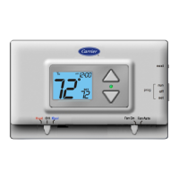
Set Clock — The Mode and Override buttons are used to
change the time and day displayed on the thermostat. Press
and hold the Mode and Override buttons for 2 seconds to
enter the setup screens. The current time will blink on and
off. Press the UPARROW and DOWN ARROW buttons un-
til the correct time is shown. Hold down the buttons to quickly
move through the time display. The AM and PM annuncia-
tors will automatically change. Hold down the Override but-
ton while pressing UPARROW or DOWNARROW to change
the time by hours instead of minutes. To ensure the sched-
ules are properly followed, make sure that AM or PM is cor-
rect for the time chosen. When the correct time is shown,
press the Mode button to modify the day of the week. The
current day will blink on and off. Press the UPARROW and
DOWNARROW buttons until the correct day is shown. Press
the Mode and Override buttons again to exit the Set Clock
mode.
Heat Pump Configuration — To configure the ther-
mostat for heat pump operation,Advanced Setup Steps 5 (Heat
Pump Operation) and 6 (Reversing Valve Polarity) must be
configured correctly. See the Configure Advanced Setup sec-
tion for information on configuring these options.
NOTE: Some large commercial rooftop heat pump units must
be configured with Advanced Setup Step 5 (Heat Pump Op-
eration) set to OFF. Refer to the base unit instructions for
more information.
W

 Loading...
