Air Purifier Sizes 1620, 1625, 2020, 2025, 2420: Installation Instructions
Manufacturer reserves the right to change, at any time, specifications and designs without notice and without obligations.
5
A11368
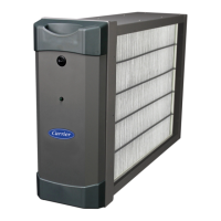
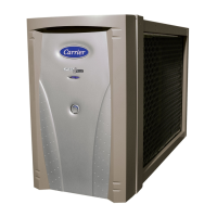
Fig. 5 – Mounting Air Purifier Cabinet
A11493
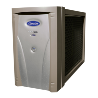
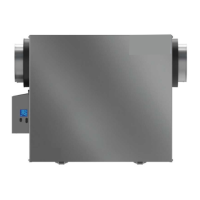
Fig. 6 – Removing Filter
A11494
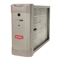
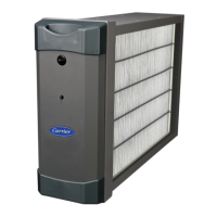
Fig. 7 – Removing FEM
A11545
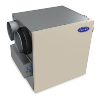
Fig. 8 – Installation of Support Foot
5. Position the cabinet between the furnace and return air duct (Fig. 3,
Fig. 4, and Fig. 5). A transition duct may be required.
On some furnaces, one or more screws may interfere with the ease
of removal of the purifier door. In this case, replace the interfering
screw(s) with pop rivet(s). Removing the screws without replacing
them with pop rivets may have an adverse effect on air sealing or
structural integrity of the furnace.
6. Use foam tape or silicone sealant between the furnace and the air
purifier cabinet.
7. Mounting holes are provided in the air purifier flanges for ductwork
and furnace attachment. To access the mounting holes on the
upstream flange of the purifier adjacent to the incoming power
wiring, the wiring cover must be temporarily removed. To do so,
remove the three screws illustrated in Fig. 9 - Step 1. Gently pull
CAUTION
!
UNIT DAMAGE HAZARD
Failure to follow this caution may result in unit damage.
Mounting holes are provided for duct work and furnace attachment.
The screws on the down-stream side of the cabinet should be installed
so that the screw heads are inside air purifier cabinet to prevent damage
to the air purifier cartridge.
 Loading...