10
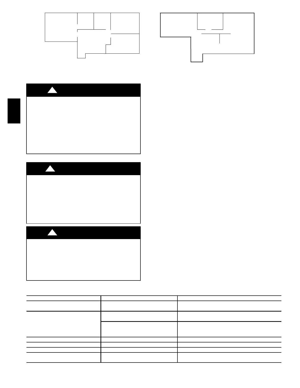
MASTER
BEDROOM
WASH-
ROOM
#1
WASH-
ROOM
#2
BEDROOM
#3
BEDROOM
#4
1220 sq ft
(113 sq m) 1220 sq ft
(113 sq m)
LIVING ROOM
#5
KITCHEN
#7
WASHROOM
#6
DINING ROOM
#8
A05359
Fig. 15 -- Floor Plan Example
UNIT COMPONENT DAMAGE HAZARD
Failure to follow this caution may result in equipment
damage or improper operation.
DO NOT use water to clean core or damage will result.
In addition, before servicing or removing the core
inspect the edges to see if they appear soft (or slightly
expanded). This can be normal and due to moisture in
the air. DO NOT handle or service core until it is dry or
air passages can become damaged and/or closed.
CAUTION
!
ELECTRICAL SHOCK HAZARD
Failure to follow this warning could result in personal
injury or death.
Before installing or servicing system, always turn off
main power to system. There may be more than 1
disconnect switch.
!
WARNING
CUT HAZARD
Failure to follow this caution may result in personal
injury.
Sheet metal parts may have sharp edges or burrs. Use
careand wearappropriateprotectiveclothing and gloves
when handling parts.
CAUTION
!
TROUBLESHOOTING
NOTE: Reference Table 3 Troubleshooting Chart
This can be a quick guide in resolving unit problems. It is also
recommended to review and understand Wall Control Board
Operation and Care and Maintenance sections before continuing.
There are3 main parts to focus on when troubleshooting ERV/HRV
unit:
1. Wall Control
2. Electronic control board
3. Blower motor
1. Wall Control
Typically, the wall control is either good or it is bad. Use Table 1 to
determine if wall control is operating correctly. Use Fig. 9 to check
control wire connections.
NOTE: The electronic control board and wall control operate on
12vdc.
2. Contro l Board
Electronic control board must havewall controlattached beforeunit
will function properly (except for units equipped with manual
switch suchas thenew horizontalunits). Outsideair thermistormust
be connected to control board for it to operate properly. See Table
6, Temperature --vs-- Ohm Chart, for valid temperature range.
3. Blower Motor
The ERV/HRV blower motor operates on 115vac, with 2-- speed
operation.
The easiest way to check blower speed operation is to use the wall
control and initiate a low--speed blower and high--speed blower
operation.
NOTE: If there is a short circuit or an open circuit at thermistor,
CPU will go into a 5 minute defrost cycle every 20 minutes. This
feature is not there on older board versions with 3pin jumpers.
Table 3—Troubleshooting Chart
SYMPTOMS CAUSES SOLUTIONS
Air too humid
Continuous exchange mode
used in small houses
Use Intermittent Mode
Check humidity level settings
Unit not responding to wall control
Defrost condition is in effect
Outdoor temperature is below 23°F
Unit will operate when not in defrost mode.
Defrost cycle is based on outdoor ambient (See Table 10)
Broken control wire
Test wa ll con t r o l
Check connections
Check thermistor
Unit stops momentarily Electrical supply interrupted Check units circuit breaker
Air from distribution register too cold Improper calibration of air flow Check calibration of flow rates
Unit makes annoying noise Ventilation wheel out of adjustment Remove the motor and screw wheel on properly
Noise level too high at distribution
registerswheninhighspeed
Air duct system too short Install a duct silencer
ERV/HRV

 Loading...


