6
% D´HUMIDITE RELATIVE HUMIDITY
´
% HUM. RELATIVE HUM.
55%
45%
35%
30%
EXT. TEMP. EXT.
MODE
MAINTENANCE
AIR EXCHANGE
ECHANGE D´AIR
´
20
25
30
40
50
60
70
80
10 C/50 F
0 C/32 F
–10 C/14 F
–20 C/–4 F
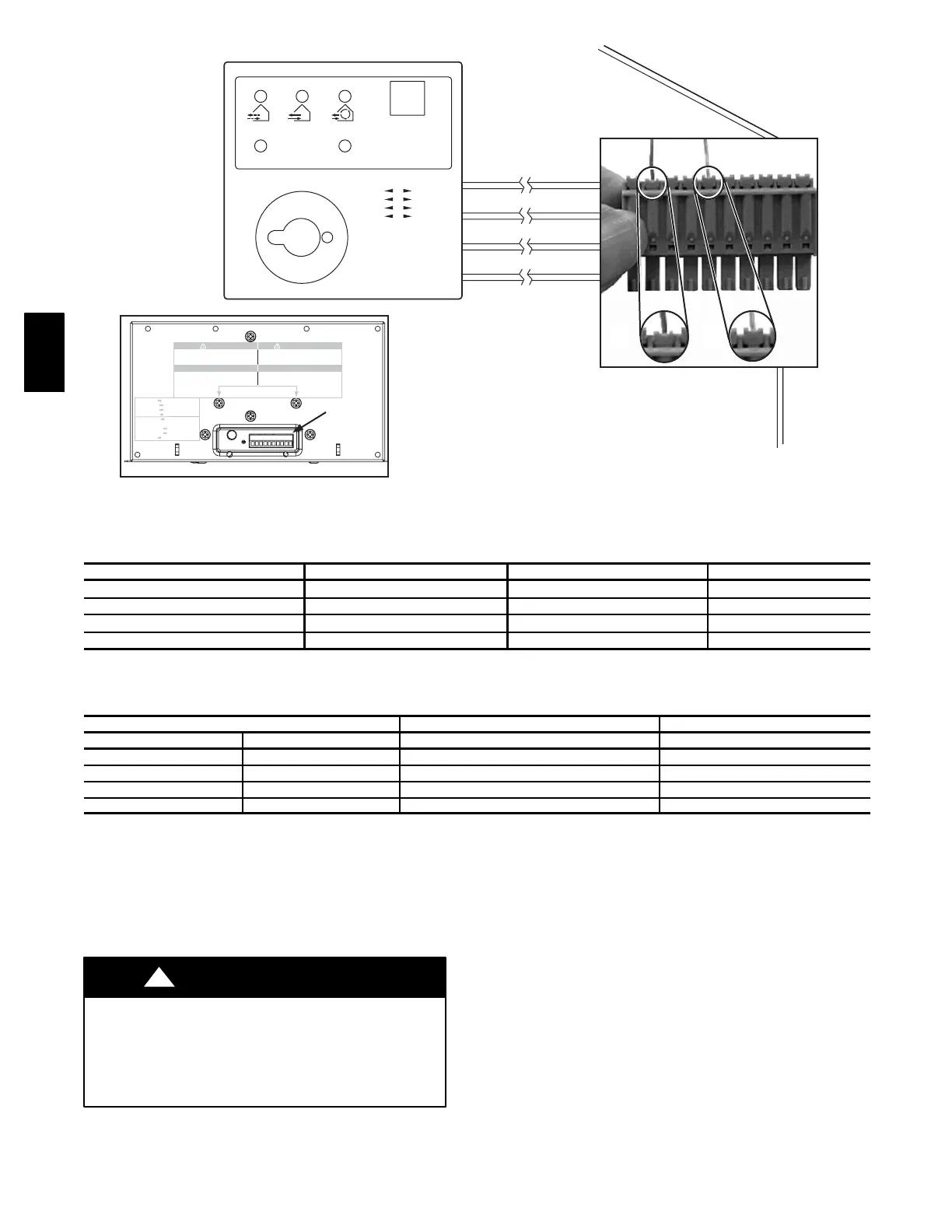
CONTROL
CONNECTOR
WALL CONTROL
YELLOW
RED
GREEN
BLACK
WARNING
Risk of electric shock. Before performing
any maintenance or servicing, alwa ys
disconnect the unit from itspower source.
AVER TISS EMENT
Dang er d’électrocution. Dé branchez
toujours l’a pp areil avant d’entreprendre
des travaux d’entretien ou de ré paration.
CA UTION
Un screw bothscrews to open the electrical
com partment. To completely remove, detach
from its retention wire inside.
ATTENTION
Dévisser les deux vis pour ouvrir le compartiment
électrique. Pour retirer complètement, le
détacher de son fil de rétention intérieur .
No light OFF or remote controled
Amber light LOW speed
Green ligh HIGH speed
Blinking light See User Manual
Sans lumière Arrêté ou contrôlé
par contrôle mura l
Lumière ambre Basse vitesse
Lumière verte Haute vitesse
Clignotant Voir guide d’utilisation
Terminal
Connector
A
B
A05334
Fig. 9 -- Control Connector
Table 1—Basic Control
MODE OPERATION DAMPER POSITION FAN SPEED
Off Off
Closed to outside
Off
Low Air exchange with outside Open to outside Low
Intermittent Air exchange with outside
Open to outside
Low
High Air exchange with outside
Open to outside
High
Table 2—Recommended Humidity Levels
OUTSIDE TEMPERATURE DOUBLE ---P ANE WINDOWS TRIPLE--- PANE WINDOWS
50° F 10° C 55 percent 65 percent
32° F 0° C 45 percent 55 percent
14° F --- 1 0 ° C 35 percent 45 percent
--- 4 ° F --- 2 0 ° C 30 percent 45 percent
--- 2 2 ° F --- 3 0 ° C 25 percent 35 percent
ELECTRICAL CONNECTIONS
1. 115-- vac Wiring
The ERV/HRV operates on 115vac. It comes with a power cord
attached to unit and ready to plug into a fused outlet. Unit must be
grounded for proper operation.
All electrical connections must comply with National and Local
Electrical Codes, or other ordinances that might apply.
ELECTRICAL SHOCK / FIRE HAZARD
Failure to follow this warning could result in personal injury,
death and/or property damage.
Do not use an extension cord as a power source for operating the
ERV/HRV.
!
WARNING
2. 12--vdc Wiring
The ERV/HRV circuit board, wall control, and accessories operate
on 12vdc. See Wall Control section, item Wiring and Fig. 8 and 9
for more information.
ACCESSORIES
1. 20 Minute Timer
A push button timer can be used to overridethe wall control and put
the ERV/HRV into high speed for 20 minutes. Connect switches in
parallel and connect leads to ERV/HRV terminals I, OC, and OL
(See Fig. 12). Push button locations are ideal in special activity
areas, such as, bathroom, or kitchen, where high-- speed exhaust
operation is needed for a short period of time.
NOTE: The 20 minute timer will not function properly unless
ERV/HRV wall control is applied and working correctly. Timing
function is internal to electronic circuit board, it is activated by a
momentary contact between OC and OL. The I connection is to
illuminate the push button. The maximum number of push button
timers that can be applied is 5.
ERV/HRV

 Loading...


