11
Table 4—Defrost Cycle
Outside Temperature
HRV Defrost Cycles
Celcius (°C) Fahrenheit (°F)
Defrosting (min.)
Operation time (min.)
between each defrost cycle
--- 5 t o --- 2 7 23 to --- 17
7 25
--- 2 7 a n d l e s s --- 1 7 a n d l e s s
10 22
Outside Temperature ERV Defrost Cycles
Celcius (°C) Fahrenheit (°F)
Defrosting (min.)
Operation time (min.)
between each defrost cycle
--- 5 t o --- 2 7 23 to --- 17
9 23
--- 2 7 a n d l e s s --- 1 7 a n d l e s s
10 22
Table 5—System Wiring Colors and Connections
CONTROL MODULE
WALL CONTROL WIRE
WALL CONTROL
Terminal Block No.
Ter m in a l B l o ck
Identification
Color Term ina l N o. Terminal Identification
J 3 --- 9 B
Black J 1 --- 4 B
J 3 --- 8 G
Green J 1 --- 3 G
J 3 --- 7 R
Red J 1 --- 2 R
J 3 --- 6 Y
Yellow J 1 --- 4 Y
Override Test
To use override test function, a thermistor must be connected to the
control board. Unit must not be in defrost mode during an override
test.
HIGH SPEED
1. Disconnect ERV/HRV from 115vac.
1. Unplug wall control wires at control module terminal block
inside ERV/HRV.
2. Plug ERV/HRV back to 115vac.
3. Attach a wire across J3--8 and J3--9 (B and G) on control
module terminal block.
4. Push in door switch, thiswill initiate a high--speed exchange.
LOW SPEED
1. Unplug ERV/HRV from 115vac.
2. Disconnect wall control wires at control module terminal
block inside ERV/HRV.
3. Plug ERV/HRV back to 115vac.
4. Connect a 3.0 K ohm resistor between B and G on control
module terminal block.
5. Push in door switch, this will initiate a low--speed exchange.
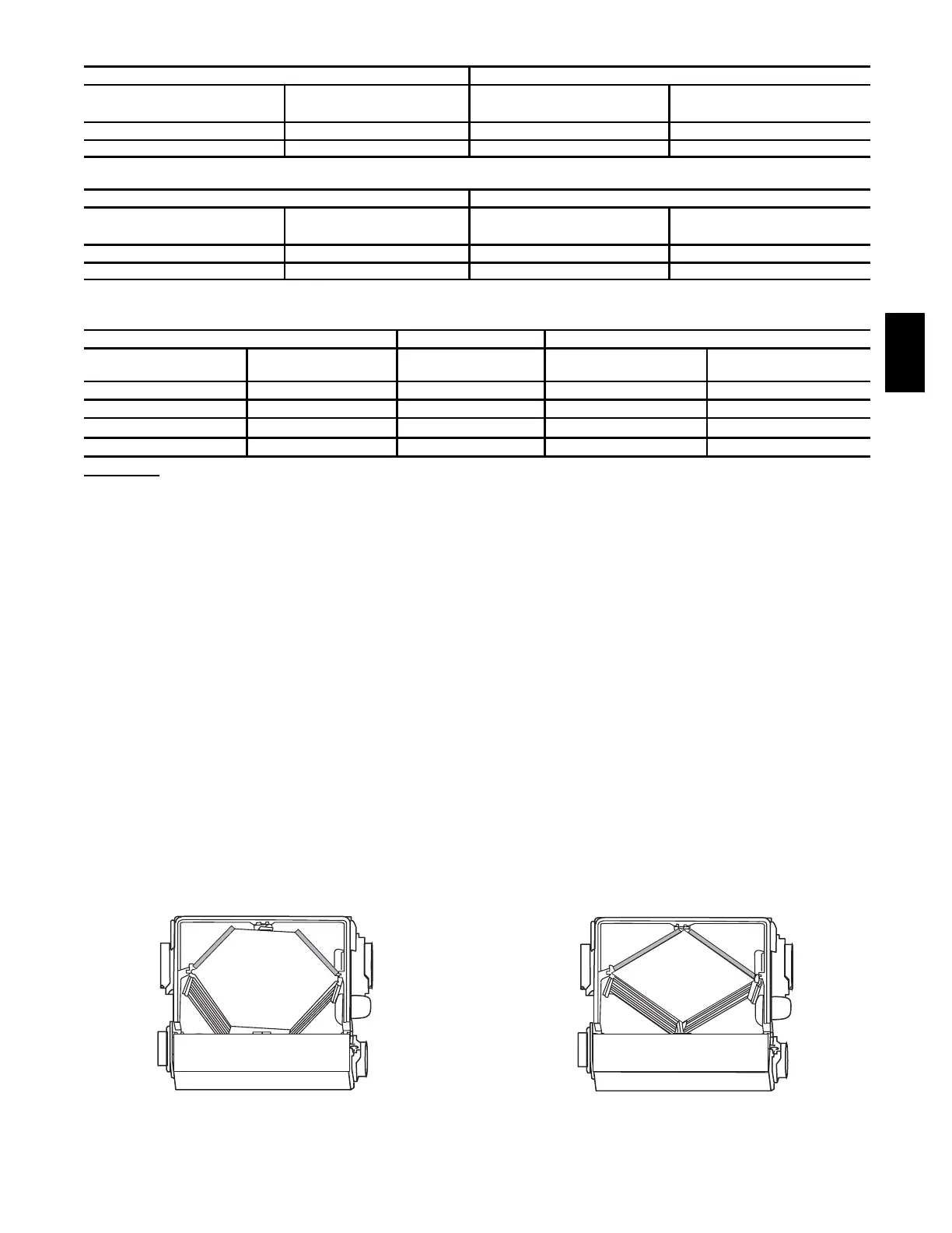
A05347
Fig. 16 -- ERV Ports on Side (Bottom View)
4. Blower Speed Selection
Three--speed blowers are factory connected to electronic control
board on HIGH-- and LOW-- speed taps of blowers. Installer can
easily change low--speed tap to medium--speed tap so electronic
control will select between high and medium speed. Connections
can be changed at motor location (See Table 6 and 7).
To change low speed to medium speed, proceed as follows:
1. Unplug unit from 115vac.
2. Locate blower assembly.
3. Locate red wire anb lue wire coming from blower assembly .
4. Unplug red wire from quick connect.
5. Unplug protecting cap quick connection from blue wire and
put on red wire coming from blower. The cap is a safety
insulator.
6. Connect red wire of main harness to blue wire.
7. Replace wires.
A05348
Fig. 17 -- HRV Ports on Side (Bottom View)
ERV/HRV

 Loading...


