7
2. 60 Minute Adjustable Timer
A 60 minute adjustable timer can also be used to override wall
control and put HRV into high--speed operation for a select amount
of time. Connect timer in parallel with push button timers, or to
ERV/HRV terminals OC and OL (See Fig. 12).
The 60 minute timer will provide a minimum of 10 minutes, and a
maximum of 60 minutes of ventilation at high speed.
BALANCING ERV/HRV
Balancing intake and exhaust airflow is very important for proper
system operation and optimum performance when applying an
ERV/HRV. Unit balancing prevents a positive and/or negative
pressure within the home. Balancing the ERV/HRV is done by
applying magnehelic gage and balancing dampers to the fresh air
intake and stale air exhaust ducts (See Fig. 11).
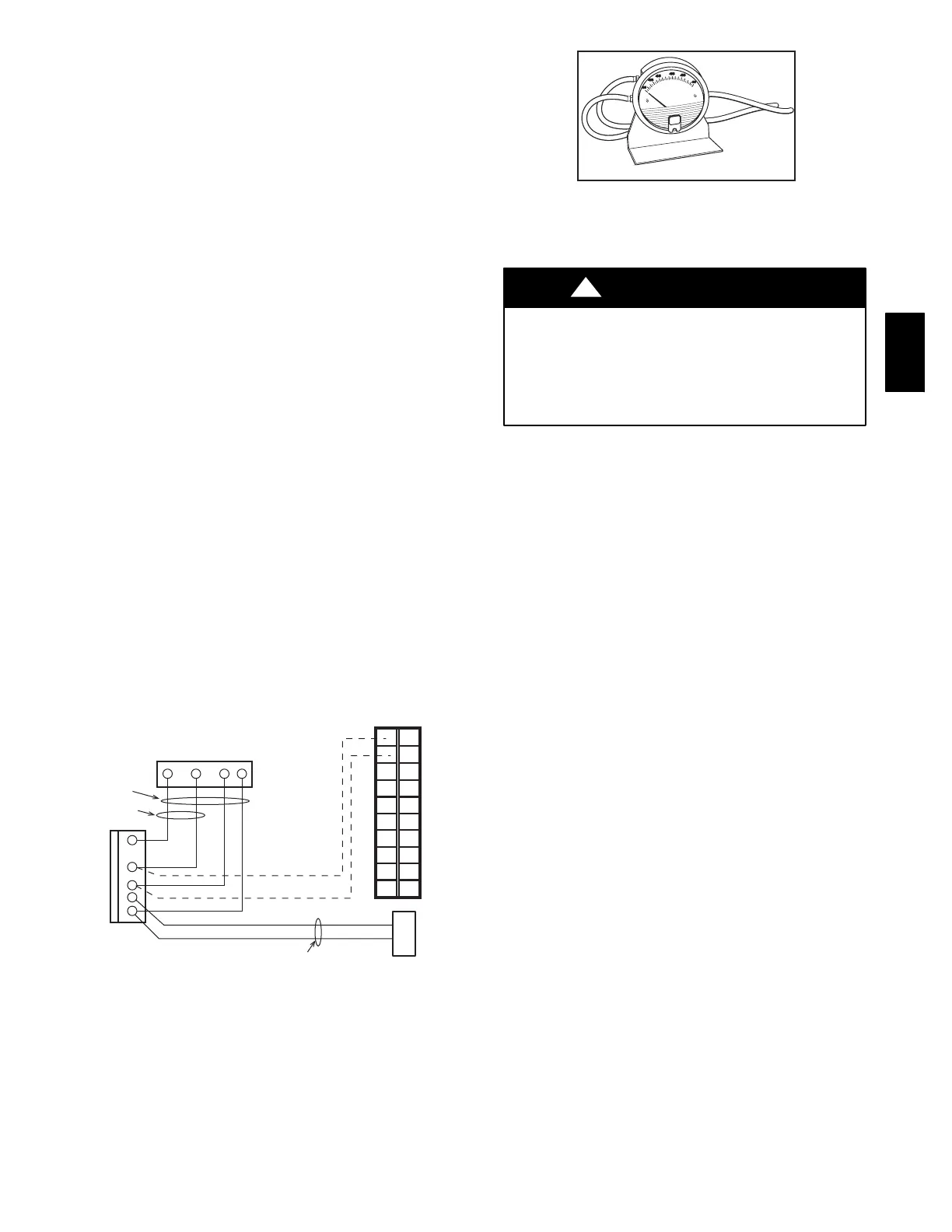
Airflow is temporarily determined by connecting a magnehelic
gage to the pressure taps on ERV/HRV (See Fig. 13). Balancing
chart is located on unit door.
If supply--air from outside is greater than exhaust--air from the
house, an imbalance can result over pressurizing the home. If
exhaust-- air is greater than supply--air, combustion appliances may
backdraft, bringing exhaust fumes into the house. A balanced
condition will ensure optimum performance, provide satisfied
customers, and avoid expensive callbacks.
Before proceeding with balancing, all windows, doors, and
fireplace flues should be tightly closed. No exhaust systems such as
range top exhausts, dryer exhaust, fume hoods, bath or roof fans
should be in operation. The forced -- air furnace (if used for
circulation) should be operating in continuous fan mode for normal
operating speed.
Step 1.—Balancing Dampers
Balancing dampers (sometimes called butterfly dampers) are
located in fresh--air intake and stale--air exhaust of the ERV/HR V.
(See Fig. 13). Some field modification may be required to ensure
proper installation of balancing dampers while located in flexible
duct. Insulating over these dampers is strongly recommended after
balancing is complete to prevent condensation problems.
W R G
Y
W
R
G
C
Y
UNIT TERMINAL CONNECTOR
THERMOSTAT
TERMINALS
FOUR
WIRES
TWO WIRES
heating only
FURNACE
24-VOLT
TERMINAL
BLOCK
TWO WIRES
NO C NC I O
C
OL Y R G B
STANDARD FURNACE INTERLOCK WIRING
CONDENSING UNIT
A05344
Fig. 10 -- Interlock Relay Wiring Layout
A98400
Fig. 11 -- Magnehelic Gage
VENTILATION EVALUATION
UNIT DAMAGE HAZARD
Failure to follow this caution may result in reduced unit efficiency,
capacity or unit life.
DO NOT use HRV during construction of a house or when
sanding drywall. This type of dust may damage system.
CAUTION
!
When ventilation requirement is determined, use Product Data
Sheets to reference unit airflow delivery and performance.
The ventilation capacity of an ERV/HRV unit while at maximum
speed is defined according to greatest total airflow required. These
methods are derived from the Canadian National Building Code
1995 version and the CSA F326.1 revision.
The following 2 methods can be used to evaluate the approximate
ventilation needs of a house.Accuracy ofcalculations aredependent
upon the information available and knowing critical measurements
of the structure (See Fig. 15).
METHOD 1
To calculate approximate ventilation:
The sum of rooms X 10 CFM per room, plus 20 CFM for a
master bedroom or basement.
Example: 8 rooms X 10 CFM + 20 CFM = 100 CFM.
NOTE: The master bedroom and basement are not included in first
part of this equation, but figured in at second part of equation.
METHOD 2
To calculate approximate ventilation:
Total cu ft X per hr = total. Take total and divide by 60 to get
CFM.
Example:
1220 sq ft X 8 ft in height = 9760 cu ft per floor
9760 cu ft x 2 floors = 19520 total cu ft in house
19520 cu ft X .3 air changes per hr = 5856 cu ft
5856 cu ft ÷ 60 minimum per hr = 98 CFM.
Conclusion: The total amount of air flow needed is 98 CFM. This
falls within airflow range of a ERVCCSHA1100 size unit.
ERV/HRV

 Loading...


