3
Step 4.— Connect Ducts to ERV/HRV
PROPERTY DAMAGE HAZARD
Failure to follow this caution may result in minor
property damage from sweating duct or loss of unit
efficiency and capacity .
If ERV/HRV duct work is installed in an unconditioned
space, insulated flexible duct is required.
CAUTION
!
Insulated flexible duct is required on both fresh-- air inlet and
exhaust--air outlet ducts connecting to exterior wall. When using
insulated flexible duct, the vapor barrier of the flexible ducts must
be taped very tight to prevent condensation problems. To reduce
pressuredrop, stretch the flex duct and support it in a proper manner
to avoid reduced airflow.
When connecting the ERV/HRV to a return--air duct system,
insulated flexible duct can be used. However, when metal or rigid
ducts are applied use approximately 18--in. of flexible duct at
ERV/HRV ports for fresh--air supply, and stale-- air return. When
using metal duct from fresh--air supply to system duct work, the
metal duct should be insulated (See Fig. 5).This can act as a silencer
when connecting ducts to return-- air duct system. This should
eliminate transmission of noise or vibration from unit to main duct
system.
FLEXIBLE
DUCT
FRESH-AIR
SUPPLY
STALE-AIR
RETURN
DUCTS CONNECTING TO
RETURN-AIR DUCT SYSTEM
A98382
Fig. 5 -- Flexible Duct Fit--Up
Step 5.—Locate and Install Exterior Hoods
IMPORTANT: To prevent condensation problems, insulated
flexible ducts are required on both fresh -- air inlet and exhaust--air
outlet ducts connecting between ERV/HRV and exterior wall.
Fresh--air intake and stale--air exhaust must be separated by at least
6 ft. Fresh--air intake must be positioned at least 10 ft. from nearest
dryer vent, furnace exhaust, driveway, gas meter, or oil fill pipe.
Fresh--air intake must be positioned as far as possible from garbage
containers and potential chemical fumes. When possible, it is
advised tolocatetheintake and exhaust hoodson sameside of house
or building. The intake and exhaust hoods should never be located
on interior corners or in dead air pockets (See Fig. 7). Both intake
and exhaust hoods must be 18 in. from ground and at least 12 in.
above anticipated snow level.
After selecting proper hood locations, make appropriate size hole
through exterior wall, pass flexible duct through hole and insert
hood tube into duct. Tape duct vapor barrier tightly around hood
tube and insert assembly back into wall and fasten securely.
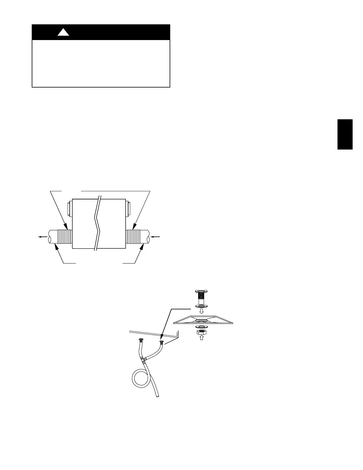
Step 6.—Condensate Drain
(For ERV, skip Step 6 and continue to Step 7.)
To connect condensate drain, proceed as follows:
1. Punch out holes in foam insulation and door, then insert
sleeved grommets into bottom of unit using the gasket
washer and nut (See Fig. 6).
2. Cut two sections of plastic tubing,about 12” long and attach
them to each drain.
3. Join the two short sections of plastic tubing to the “T”
connector and the main tube as shown.
4. Make a loop in the tubing below the “T” connector to create
a trap to prevent sewer gases from entering the ventilation
system (See Fig. 6).
5. Connect unit drain to building’s main drain. Provide slight
slope from unit for run--off.
A99268
Fig. 6 -- Condensate Drain With Loop Trap (HRV Only)
ERV/HRV

 Loading...


