FCM/A5, FEV, FJM, FEM4, FHMA5, FMA4/5, FM(C,U)5, FS(A,M,U)4, FTMA5, F(V,X)M4, F5M4, REM4, WA(H,M,P,X) WB(G,H)L, WC(G,H)L: Service and Maintenance
Manufacturer reserves the right to change, at any time, specifications and designs without notice and without obligations.
16
No further fan coil troubleshooting information will be available at the
User Interface until communications are reestablished.
Check system wiring to be sure Observer wall control is powered and
connections are made Dx+ to DX+, DX- to DX-, etc. and wiring is not
shorted. Mis-wiring or shorting of the DX+, DX-, C, R communications
wiring will not allow successful communications.
Shorting or mis-wiring the low voltage system wiring will not cause
damage to fan coil control or to User Interface but may cause the low
voltage fuse to open.
STATUS CODE 46, BROWNOUT CONDITION:
If the secondary voltage of the transformer falls below 15VAC for a
period exceeding four seconds, Status Code 46 will be displayed on
STATUS LED.
If system includes a non-communicating outdoor air conditioner or heat
pump, the User Interface will command the fan coil to turn off Y output
controlling compressor.
When secondary voltage rises above 17VAC for more than four seconds,
the brownout condition is cleared and normal system operation will
resume subject to any minimum compressor off delay function which
may be in effect. Brownout does not affect blower or electric heater
operation.
STATUS CODE 53, OUTDOOR AIR TEMPERATURE SENSOR
FAULT:
If an OAT sensor is found at power-up, input is constantly checked to be
within a valid temperature range. If sensor is found to be open or shorted
at any time after initial validation, Status Code 53 will be displayed at
amber STATUS LED.
Check for faults in wiring connecting sensor to OAT terminals. Using an
Ohmmeter, check resistance of thermistor for a short or open condition.
If thermistor is shorted or open, replace it to return the system to normal
operation. If fault is in the wiring connections, correcting the fault will
clear the code and return the system to normal operation.
NOTE: If fault condition is an open thermistor or a wiring problem that
appears to be an open thermistor and the power to the fan coil control is
cycled off, the fault code will be cleared on the next power-up but the
fault will remain and system operation will not be as expected. This is
because on power-up, the fan coil control cannot discern the difference
between an open sensor or if a sensor is not installed.
Emergency Heating and Cooling Modes
Fan coil control can provide emergency heating or cooling using a
common heat/cool thermostat in the event that there are no system
communications, fault is in User Interface and no replacement is
immediately available.
To activate these modes, the thermostat and outdoor unit must be wired
as a common heating/cooling system to fan coil control RYWC
terminals. Fan coil control must be powered and displaying Status Code
16, System Communication Fault.
NOTE: These emergency modes do not provide the level of comfort and
efficiency expected by the consumer and should only be activated when
User Interface cannot be replaced immediately.
SEQUENCE OF OPERATION
The FCM fan coil is designed for installation with a communicating
User Interface. This fan coil will not respond to commands provided by
a common thermostat except under certain emergency situations
described in the Start Up and Troubleshooting sub-section.
The User Interface uses temperature; humidity and other data supplied
from indoor and outdoor system components to control heating or
cooling system for optimum comfort.
ADVANCED TROUBLESHOOTING:
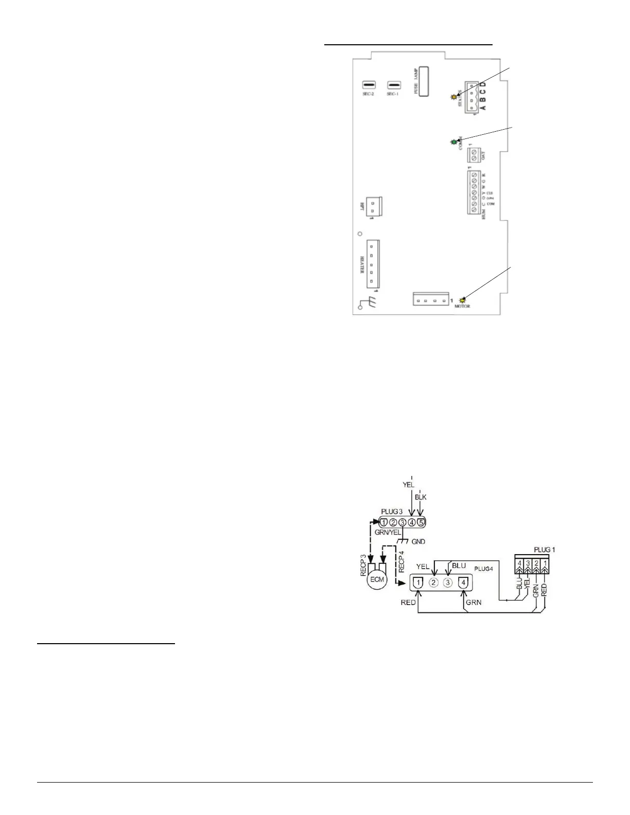
A13030
Fig. 12 – Circuit Board LED Locations
Troubleshooting the FCM Fan Coil Circuit Board:
– Production Unit circuit board Fan Coil part number 1184554
Primary test that should be performed:
Motor Line Voltage Check
1. Turn off power (240V).
2. Remove Plug 3 from ECM motor
3. Turn on power.
4. Check Plug 3, terminals 4 and 5, to ensure there are 240V.
5. Turn off power.
6. Reconnect Plug 3 to motor.
A13031
Fig. 13 – ECM / Plug Wiring Diagram
The following troubleshooting techniques will assist in determining the
correct component to replace when the Fan Coil Board presents a Fault
Code 44 or 41:
1. Disconnect power from the unit (240V).
2. Disconnect the DX+, DX-, C, R connector from the board.
3. Disconnect Plug 1 from the board (Fig. 13).
4. Turn on power (240V).
5. After reestablishing power, you should receive Fault Code 44, and
the motor LED should be off.
Status
LED
Communication
LED
Motor
LED