FCM/A5, FEV, FJM, FEM4, FHMA5, FMA4/5, FM(C,U)5, FS(A,M,U)4, FTMA5, F(V,X)M4, F5M4, REM4, WA(H,M,P,X) WB(G,H)L, WC(G,H)L: Service and Maintenance
Manufacturer reserves the right to change, at any time, specifications and designs without notice and without obligations.
14
A12231
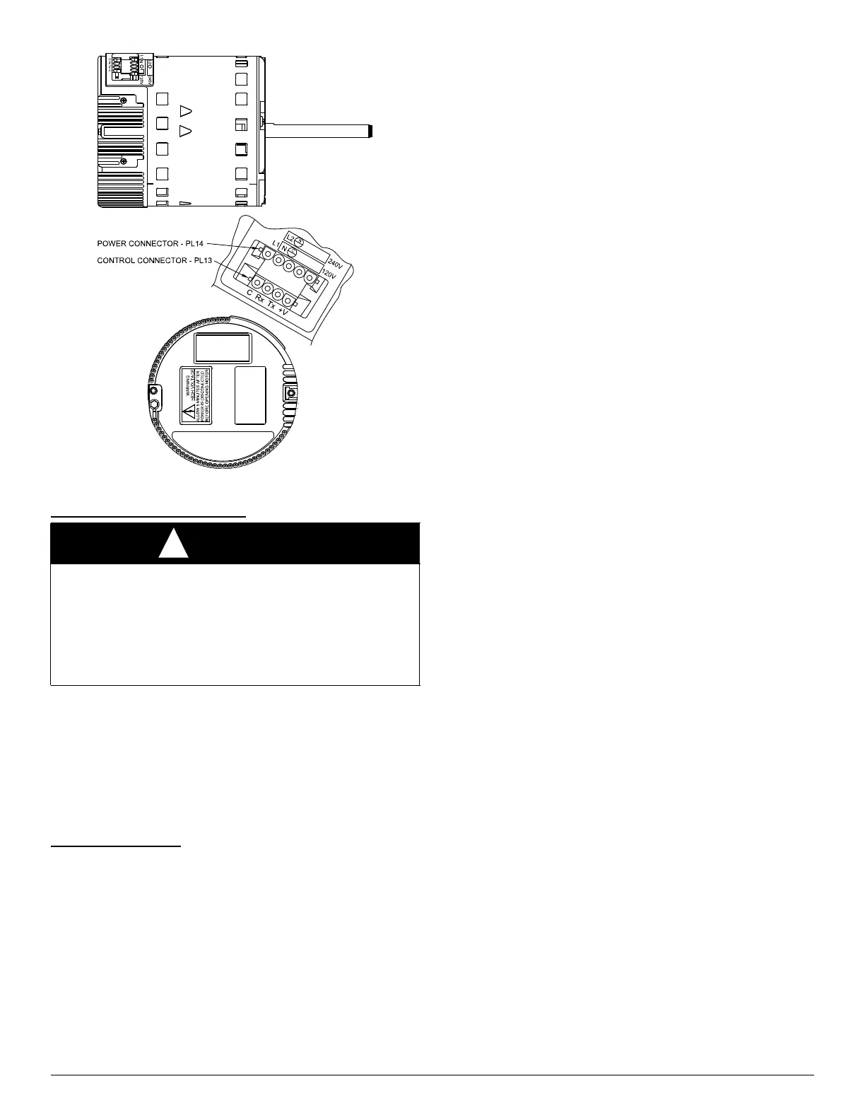
Fig. 11 – FCM ECM Motor
Vefify Motor Winding Section
Before proceeding to replace a motor control module:
1. Check motor winding section to be sure it is functional.
2. Remove motor control module section and unplug winding plug.
Motor shaft should turn freely, resistance between any two motor
leads should be similar and resistance between any motor lead and
unpainted motor end should exceed 100,000 ohms.
3. Failing any of these tests, entire ECM motor must be replaced.
4. Passing all of the tests, motor control module alone can be replaced.
Motor Turns Slowly
1. Low static pressure loading of blower while access panel is
removed will cause blower to run slowly. Particularly at low
airflow requests. This is normal, do not assume a fault exists.
2. Recheck airflow and system static pressure using User Interface
service screens with access panel in place.
NOTE: Blower motor faults will not cause a lockout of blower
operation. Fan coil control will attempt to run the blower motor as long
as User Interface maintains a demand for airflow. Fan coil control will
not operate electric heaters while a fault condition exists. The fan coil
control communicates with the motor at least once every five seconds,
even when the motor is idle. If, during operation, the fan coil control
does not communicate with the motor for more than 25 seconds, the
motor will shut itself down and wait for communications to be
reestablished.
Using Motor LED in Troubleshooting
The MOTOR LED is connected to the blower motor communication line
and works with the fan coil control microprocessor and the STATUS
LED to provide fan coil operation and troubleshooting information.
When the motor is commanded to operate, the MOTOR LED will be
turned on and will flash each time instructions are sent to the motor.
When the motor is commanded to stop, the MOTOR LED will be turned
off.
If the MOTOR LED is lit, flashing and the motor is running or if the
MOTOR LED is off and the motor is stopped, operation is normal and
no motor fault exists.
If the MOTOR LED is lit, flashing and the motor does not run, or if the
MOTOR LED is off and the motor is running, check the STATUS LED
for the Status Code. Refer to the troubleshooting instructions for the
indicated Status Code in Section E, Fan Coil Troubleshooting.
Fan Coil Troubleshooting
Fan coil faults indicated by flashing codes on the amber system STATUS
LED can be resolved using troubleshooting information provided below.
Codes are listed in order of their priority, highest to lowest. Though
multiple faults can exist at any time, only the highest priority code will
be displayed on STATUS LED. Clearing the indicated fault when
multiple faults exist will cause the next highest priority Status Code to be
flashed. All existing faults, as well as a fault history, can be viewed at
User Interface.
STATUS CODE 45, CONTROL BOARD TEST FAULT:
Fan coil control has failed internal start-up tests and must be replaced.
No other service procedure will correct.
STATUS CODE 37, HEATER OUTPUT SENSED “ON” WHEN NOT
ENERGIZED:
Fan coil control is provided with circuitry to detect presence of a 24VAC
signal on Electric Heater stage 1 and stage 2 outputs.
If fan coil control detects a 24VAC signal on either heater stage output
and it is not supplying signal, Status Code 37 will be displayed on
STATUS LED. Fan coil control will turn off output and command
blower motor to supply an airflow determined to be safe for current
operation mode with electric heaters energized.
To find the fault:
1. Stop all system operations at User Interface and check heater stage
24VAC outputs.
2. Disconnect electric heater at plug/receptacle 2 and check heater
wiring for faults. See Status Code 36 for more information.
STATUS CODE 44, MOTOR COMMUNICATION FAULT:
The MOTOR LED is connected to the blower motor communication line
and works with the fan coil control microprocessor and STATUS LED to
provide fan coil operation and troubleshooting information.
When motor is commanded to operate, the MOTOR LED will be turned
on and will flash each time instructions are sent to the motor.
When the motor is commanded to stop, the MOTOR LED will be turned
off. The MOTOR LED will not flash to indicate communications when it
is turned off.
Fan coil control is constantly communicating with the motor, even when
the motor and MOTOR LED are off. If motor does not acknowledge
receipt of communications, the control will display Status Code 44 on
STATUS LED and continue to try to communicate with the motor. If
motor acknowledges communication, status code will be cleared.
If MOTOR LED is lit and flashing and motor does not run:
1. Check the STATUS LED. If STATUS LED is indicating a Status 44
code, check the motor wiring harness for proper connection to
control and motor receptacles.
WARNING
!
ELECTRICAL SHOCK HAZARD
Failure to follow this warning could result in personal injury or death or
possible equipment damage.
After disconnecting power from the ECM motor, wait at least five
minutes before removing the control section. Internal capacitors require
time to discharge. Minor injury from electrical shock may result from
early contact with live metal parts.