FCM/A5, FEV, FJM, FEM4, FHMA5, FMA4/5, FM(C,U)5, FS(A,M,U)4, FTMA5, F(V,X)M4, F5M4, REM4, WA(H,M,P,X) WB(G,H)L, WC(G,H)L: Service and Maintenance
Manufacturer reserves the right to change, at any time, specifications and designs without notice and without obligations.
24
until the last heater de-energizes. The Time Delay Printed Circuit Board
(PCB) is a logic controlled time delay activated by low-voltage control
signal (G) from thermostat. The PCB includes a normally open relay
which closes to energize the blower motor when the G terminal is
energized. Then when the G terminal is de-energized the relay
energizing the blower motor remains closed for 90 – 100 seconds before
opening.
Relays
Later production EHK2 heaters have relays controlling the heater
elements instead of sequencers. A small rectifier PCB is mounted to
each relay which converts the incoming 24VAC control signal to DC.
In addition to the rectifier circuit, the second and third stage relays
contain a time-on delay circuit of five seconds for second stage, and
eight seconds for third stage. When the control signal is removed from
the relays, all relays will open with no time-off delay.
Leak Dissipation System
Operation (Models with R-454B Refrigerant)
When no leak is detected, G, Y, and W pass through the dissipation board
and operate normally. In this state, the Dissipation Board Status LED
remains solid yellow. When the A2L Detection Sensor reaches a
threshold of detected R-454B refrigerant, the Status LED flashes one
time and the dissipation board enters dissipation mode. While the
detected refrigerant is over the threshold, the Status LED will continue to
flash a Fault Code of 1. After the level is lower than the threshold, the
Status LED flashes a code of 3 as the dissipation board completes its
dissipation actions. These actions include de-energizing Y and W and
energizing G for 15 minutes. After the 15 minutes if the refrigerant
detected is below the threshold, there is a 5 minute delay before
returning to normal operation. If the refrigerant detected is above the
threshold, G continues to be energized until refrigerant is below the
threshold. At that point the 5-minute delay begins.
After dissipation is complete, the unit returns to normal operation with
the Status LED being solid.
System Self-Test
Power on the unit and verify proper functioning of equipment. The
yellow LED on the dissipation board should be steady. If flash codes are
present, see (Troubleshooting on p24).
NOTE: Operation of the Test Mode is only possible if no faults exist on
the dissipation board.
IMPORTANT: Press the Test button for roughly ONE SECOND to
enter Test Mode. Pressing the Test button for a longer periods enables
different functions (Table 11).
Press the Test button on the dissipation system control board to ensure
proper dissipation system operation under each test condition listed
below. After pressing the Test button, system will enter Dissipation
Mode for 60 seconds to help verify correct operation.
Ensure that the fan coil is able to meet the minimum required dissipation
mode airflows. These required minimum airflow rates during
Dissipation Mode are listed in Table 13. They are based on the total
system refrigerant charge quantity.
Troubleshooting
For all flash codes, first try power cycling the system to remove the
code. Refer to Table 14 and Table 15.
No power
Verify the wiring to/from pins 1 and 8 on the power harness plug. Check
the 24V system wiring from the transformer.
Flashing 1
Check for refrigerant leaks using an independent R-454B detector. If no
leaks are present, replace the sensor.
Flashing 2
Check both ends of the sensor wire harness to ensure proper attachment.
Power cycle the system to check whether the flash code has been
removed. If the flash code is still present, replace the sensor.
Flashing 3
Check for refrigerant leaks using an independent R-454B detector.
Flashing 4
If the code does not clear after power cycling the system, replace the
dissipation board.
Flashing 5
If the code does not clear after power cycling the system, replace the
sensor.
Flashing 6
Press the test button repeatedly. Power cycle the system. If the button
cannot be reset, replace the dissipation board.
Flashing 7
Verify wiring of all "Y" and "W" wires in the applicable wiring diagram.
Table 11 – Dissipation Board Test Button Functions
Hold Button Time (sec) Function
1 - 4 Dissipation Mode for 60 seconds
5 - 29 Display flash code history
30+ Flash code 6
3 rapid presses Clear flash code history
Table 12 – Required Operational Checks to Ensure Proper
Dissipation System Function
Normal Operation
Test # T-Stat Call Compressor Indoor Fan
Electric/Gas
Heat
1 None Off Off Off
2 Cool On On Off
3 Heat Off On On
Dissipation Activated
4 None Off On Off
5 Cool Off On Off
6 Heat Off On Off
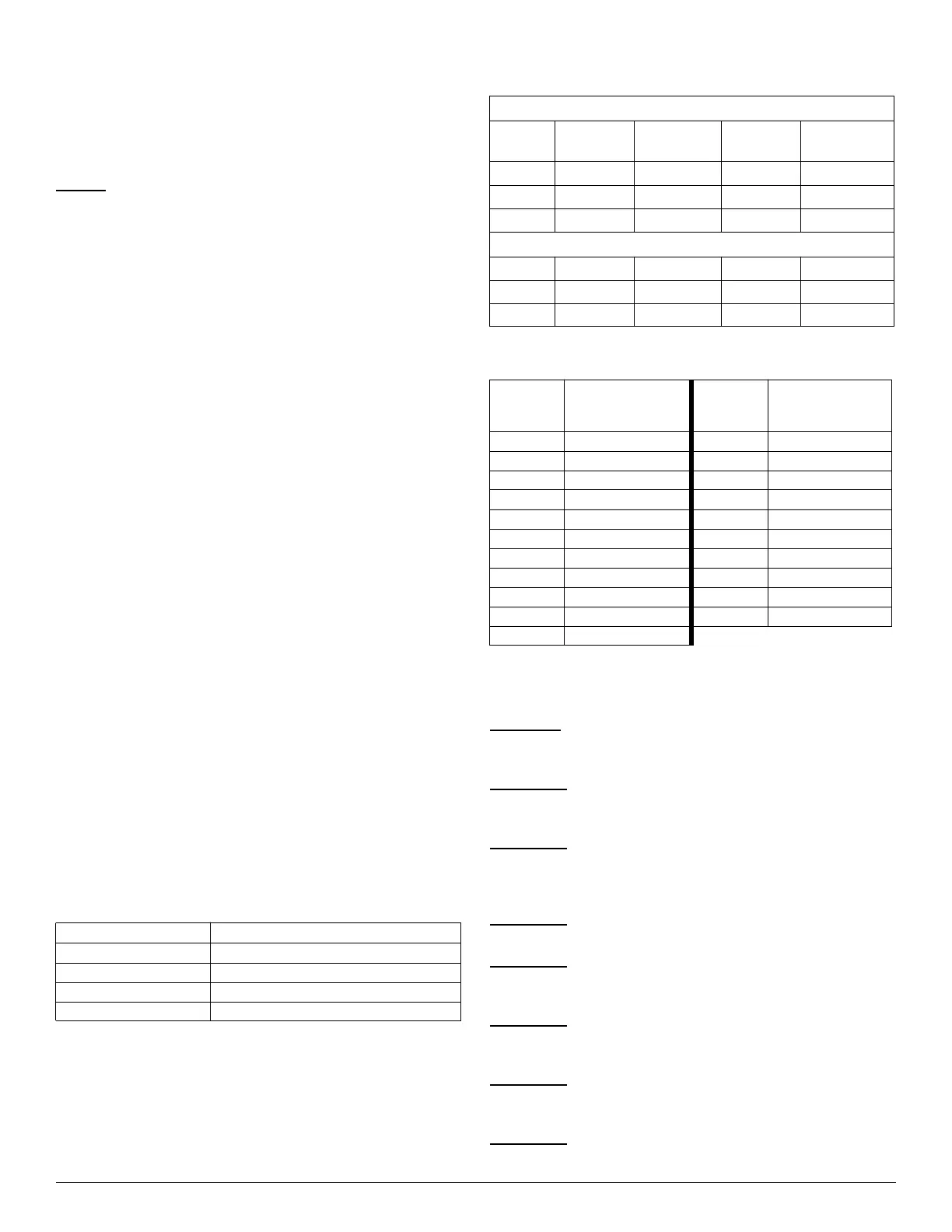
Table 13 – Required Minimum Dissipation Mode Airflows,
based on Total System Refrigerant Charge Quantity
Total
System
Charge (lb)
Minimum Required
Dissipation Airflow
(CFM)
Total
System
Charge (lb)
Minimum Required
Dissipation Airflow
(CFM)
5 133 16 426
6 160 17 452
7 186 18 479
8 213 19 505
9 239 20 532
10 266 21 559
11 293 22 585
12 319 23 612
13 346 24 639
14 372 25 665
15 399